

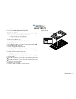


KE-50XBR900(UC)
3-1
SECTION 3
TROUBLESHOOTING
1
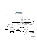
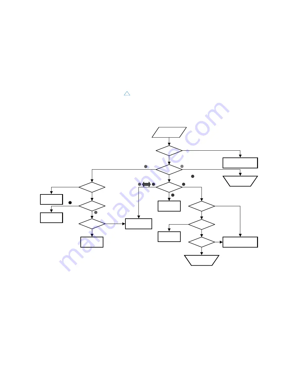
3-1. DISPLAY UNIT (PDM-5000)
No image
appears.
LED display
Panel module
failure
Blinks alternately.
Blinks six times.
Blinks four times.
G board failure
Temperature sensor
or circuit failure
Just after
start?
YES
NO
Installation
environment?
OK
NG
Fan rotation?
YES
NO
Fan or
circuit failure
Environment
improvement
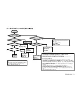
Blinks.
Just after
start?
YES: Not appear at all.
NO: Appears for a few seconds.
LED display
Lights.
BOX LED
Blinks nine times.
Encrypted authentication
error of box or display
All is normal.
Box LED?
LED display
Lights.
Image erasure
mode
Box failure
Abnormal
Lights.
Priming?
YES: Light emission
NO: No light
emission
P board failure
Check of cable
connection
Summary of Contents for WEGA KE-50XBR900, KE-42XBR900
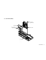
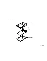
Page 18: ...KE 50XBR900 UC 1 9 1 2 3 H4 BOARD REMOVAL 1 Two screws BVTP 3X12 2 H4 Board Front panel ...
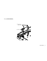
Page 19: ...KE 50XBR900 UC 1 10 1 2 4 H3 BOARD REMOVAL 1 Three screws BVTP 3X12 2 H3 Board Front panel ...
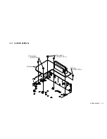
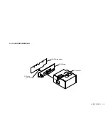
Page 21: ...KE 50XBR900 UC 1 12 1 2 6 H2 BOARD REMOVAL 1 Two screws M 3X8 P SW 2 H2 Board ...
Page 23: ...KE 50XBR900 UC 1 14 1 2 8 B BLOCK ASSY REMOVAL 1 B Block assy ...
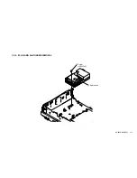
Page 24: ...KE 50XBR900 UC 1 15 1 2 9 M AD AND AU BOARDS REMOVAL 2 Shield case 1 Screw PSW 3x8 ...
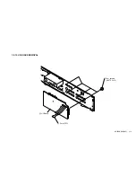
Page 28: ...KE 50XBR900 UC 1 19 1 2 13 U1 BOARD REMOVAL 1 Four screws BVTP 3x12 2 U1 Board 3 Core FPC ...
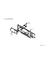
Page 29: ...KE 50XBR900 UC 1 20 1 2 14 U2 BOARD REMOVAL 1 Tow screws BVTP 3x12 2 U2 Board Rear panel ...


