5
EN
ANTENNA B
TNNER OUTPUT(LINE LEVEL 0dBm)
MIX OUTPUT
IN(DC 9V OUT)
5
6
4
3
2
1
ATT
0
10dB
ANTENNA A
AC IN
IN(DC 9V OUT)
ATT
LEVEL
0
10dB
LINE
0dBm
MIC
–38dBm
⁄
3
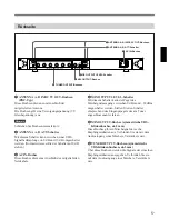
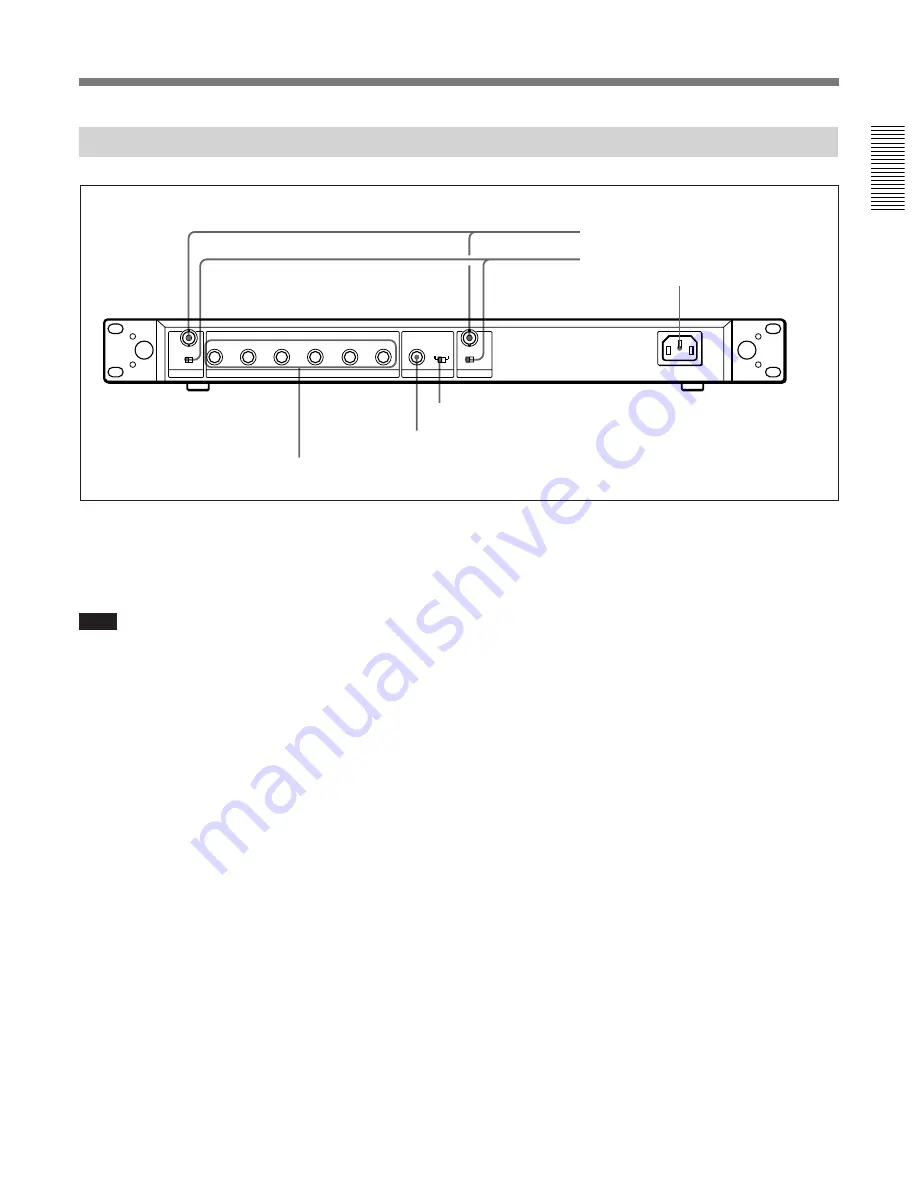
AC IN connector
4
MIX OUTPUT LEVEL switch
5
MIX OUTPUT connector
6
TUNER OUTPUT connectors
2
ANTENNA A, B ATT switches
Rear Panel
1
ANTENNA A, B IN/DC 9V OUT (antenna A, B
input/DC power output) connectors (BNC type)
Connect the supplied antenna.
These connectors output 9V DC power.
Note
Never short-circuit these connectors.
2
ANTENNA A, B ATT (attenuation) switches
Select the RF attenuation as 0 dB or 10 dB. (Normally,
set the switches to 0 dB.)
3
AC IN connector
Connects to an AC power source with the supplied AC
power cord.
4
MIX OUTPUT LEVEL switch
Selects the mixed output level as 0 dBm or –38 dBm.
Set this switch according to the input level of the
equipment connected to the tuner.
5
MIX OUTPUT connector (ø6.3 phone balanced
(TRS))
Supplies mixed audio signals of six tuner units. You
can connect this to the audio input connector of a
mixer, amplifier or similar equipment.
6
TUNER OUTPUT (tuner sound output)
connectors (ø6.3 phone balanced (TRS))
Each connector supplies the audio signal from the
corresponding tuner unit. You can connect this to the
audio input connector of a mixer, amplifier, or similar
equipment.
1
ANTENNA A, B IN/DC 9V OUT connectors
Summary of Contents for WRR-801A
Page 15: ......


