1-3
WRR-802A (U)
7
US
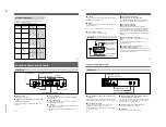
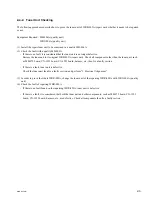
Here is explained channel setting for the U68 model as an
example.
Take the following precautions to prevent interference and
noise.
• If there is a TV broadcasting station nearby, to avoid
possible interference from its broadcasting, do not use that
station’s channel.
• When simultaneously using two or more tuners, always set
the tuners to different channels within the same group
(other than group 00).
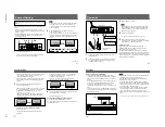
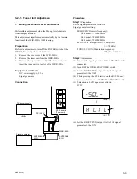
1
Turn the POWER switch on.
The message “U 68” appears on the display, and then
the current status of this unit is displayed.
Note
Turn the POWER switch on after reducing the volume
of equipment connected to the TUNER OUTPUT
connector. Otherwise, noise will be heard when the
power is turned on.
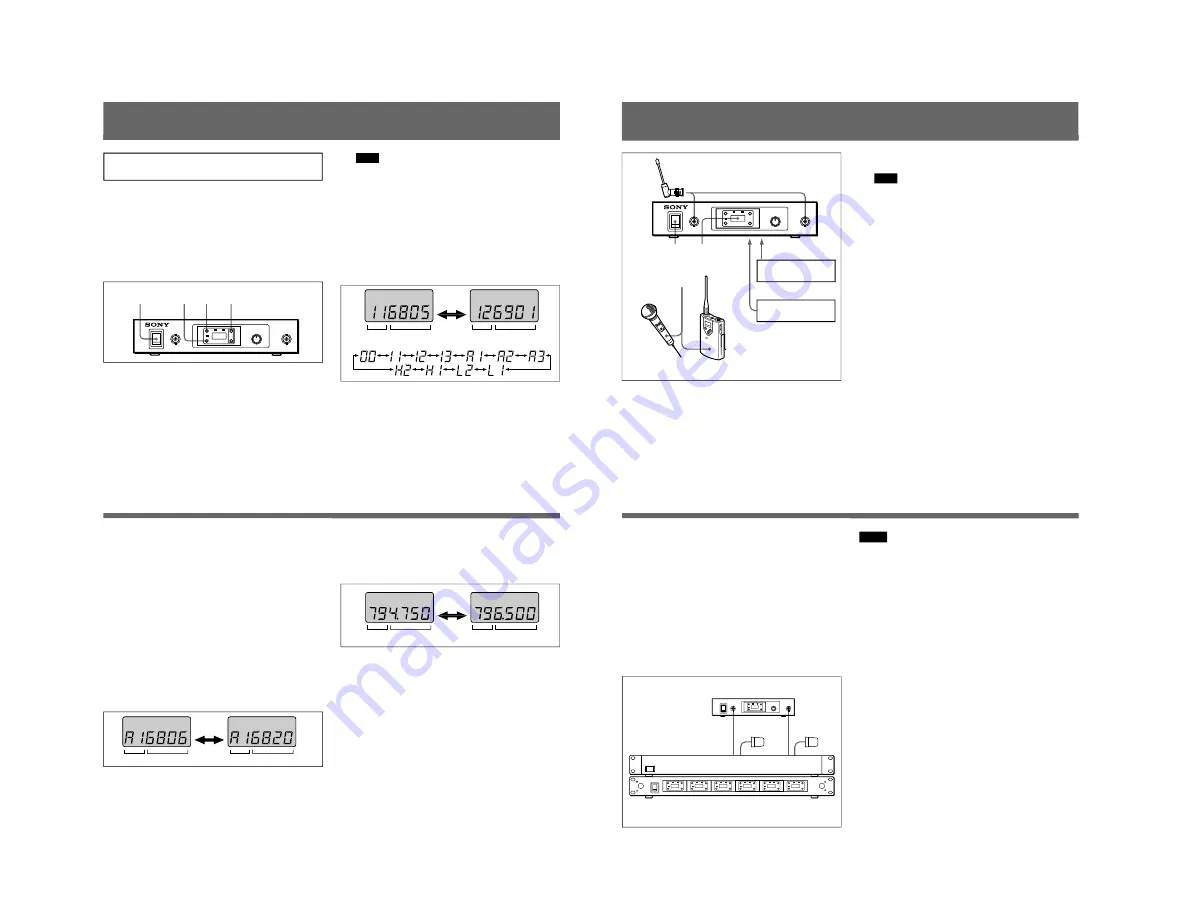
2
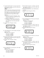
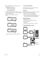
While holding down the GP button, press the + or –
button to select a group.
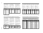
Each time you press the + or – button, the GP indication
changes as shown in the following figure. To change the
indication continuously, press and hold down the + or –
button.
Channel Setting
GP
CH
GP
CH
+
–
1
3,4 2
2,3,4
(Continued)
8
US
The CH indication shows the lowest frequency channel
of the selected group. For group 00, however, the
channel selected last is displayed.
Releasing the buttons automatically cancels the group
selection mode, and the currently displayed group is
selected.
3
While holding down the CH button, press the + or –
button to select a channel.
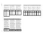
Similar to step
2
, each time you press the + or – button,
the CH indication changes in the order shown in the
group and reception channel list. (See “Wireless
Channel Lists” on page L-1.)
If you press the + button when the last channel of the
selected group is displayed, the first channel of the
group will be displayed.
Selecting the reception channel by frequency
Press the + button.
This changes the GP/CH indication to a frequency
indication.
To change a frequency, press the + or – button while
keeping the CH button pressed. (A higher or lower
frequency will be displayed.)
Press the + button again to change the frequency
indication back to a GP/CH indication.
4
If the desired channel or frequency is displayed, release
the CH button and + or – button.
The selected channel is set.
To store the selected group and channel
Leave the indication unchanged for 1 second.
The group and channel set in the procedure explained above
are stored in memory.
Channel Setting
GP
CH
GP
CH
+
–
GP
CH
GP
CH
+
–
9
US
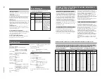
1
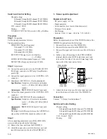
Connect the supplied antennas and make the antenna
tips point upward.
2
Connect the supplied AC power adaptor to the DC IN
9V connector and an audio mixer or amplifier to the
TUNER OUTPUT connector.
ANTENNA A, B
Audio mixer, amplifier
AC power adaptor
UHF synthesized
transmitter
UHF
synthesized
wireless
microphone
DC IN 9V
TUNER OUTPUT
5
3
4
1
2
+
–
Operation
3
Turn the POWER switch on.
Note
Turn the POWER switch on after reducing the volume
of the equipment connected to the TUNER OUTPUT
connector. Otherwise, noise will be heard when the
POWER switch is turned on.
4
Set the reception channel.
For details on setting the channels, see page 7.
5
Turn on the wireless microphone or transmitter.
Use the wireless microphone or transmitter to which the
same channel is assigned as to this unit.
If noise is heard
Depending on the environment where the system is
installed, outside noise or radio wave may disrupt the
transmission of certain channels.
To select a channel under this circumstance, turn off the
wireless microphone or transmitter. Then select a channel at
which the RF indicator is off. (A channel free from noise or
radio wave interference is selected.) Set the same channel on
the microphone or transmitter.
10
US
1)
The distance depends on the operating environment and conditions.
WRR-802A
AN-820A
WD-820A
Tuner
a) Coaxial cable (30 m (100 feet))
a)
a)
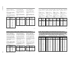
Notes on using with a WD-820A
• This unit does not supply the internal booster of the
optional AN-820A UHF Antenna through the ANTENNA
A,B connectors. It is impossible to connect the AN-820A
directly.
• When adding the WRR-802A by cascade connection to a
tuner system containing the WD-820A UHF Antenna
Divider, use a coaxial cable (5D-2V, RG-212/U or
equivalent) with length of 30 m (100 feet) as shown in the
figure.
• To avoid noise, remove the transmitter from the antennas
as far as possible when setting the channel or waiting with
the transmitter powered.
Notes
• Do not simultaneously use two or more microphones and
transmitters that are set to the same channel.
• Separate the reception antennas and the transmitter by
more than 3 m (9 feet 11 inches).
• The number of wireless microphone channels actually
usable in a multi-channel system may be smaller than the
normal capacity of that system if there is interference from
TV broadcasting or other RF signals.
• When operating two or more UHF wireless microphone
systems using the same wireless channel in the same
group, ensure that the systems are at least 100 m (330
feet)
1)
apart as far as they are installed within sight of each
other.
Operation


