background image

4

GB

• Do not drag the TV Sound Bar System-installed 

TV. The base part may come off and damage the 
floor.

• When carrying the TV Sound Bar System-

installed TV, do not hold it by the TV Sound Bar 
System. Doing so may cause damage or injury.

Notes on installation

• When assembling, spread a cloth on the floor to 

avoid damaging the floor.

• Install the products on a solid and flat floor.
• Be sure that two or more persons install the 

products. Doing it alone may result in an accident 
or injury.

• Be sure to keep children away during the process.

Be sure to install the products 
securely following the 
instructions.

• Tighten the screws securely. If the TV Sound Bar 

System is not installed securely, it may fall and 
cause damage or injury.

• Be careful not to pinch your fingers or hands when 

assembling the products.

Notes on cleaning

Clean with a soft cloth slightly moistened with a 
mild detergent solution. Do not use any type of 
abrasive pad, scouring powder or solvent such as 
thinner, benzine or alcohol.
If you have any questions or problems concerning 
this product, please consult your nearest Sony 
dealer.

Notice for customers: The 
following information is only 
applicable to equipment sold in 
countries applying EU 
Directives.

The manufacturer of this product is Sony 
Corporation, 1-7-1 Konan Minato-ku Tokyo, 


108-0075 Japan. The Authorized Representative for 
EMC and product safety is Sony Deutschland 
GmbH, Hedelfinger Strasse 61, 70327 Stuttgart, 
Germany. For any service or guarantee matters 
please refer to the addresses given in separate 
service or guarantee documents.

Table of Contents

Unpacking ...................................... 5

Setting Up ...................................... 6

Installing the TV Sound Bar System 


on the TV stand ..................................... 6

Preventing the TV from toppling over... 11
Adjusting the angle of the TV................ 13

Specifications .............................. 14

Downloaded from 

ManualsNet.com

 search engine

Summary of Contents for WS-32SE1B

Page 1: ...1 Sony Corporation 4 269 373 12 1 Speaker Attachment Bracket WS 32SE1B WS 40SE1B WS 46SE1B Operating Instructions Mode d emploi Manual de instrucciones GB FR ES Downloaded from ManualsNet com search engine ...

Page 2: ... over or the product dropping Be sure to observe the precautions for safety to prevent such accidents If the following precautions are not observed serious injury or death through fire or electric shock the product toppling over or falling can result Do not drop the products or install them where there is a possibility of them falling down Be sure to subcontract installing moving or dismounting th...

Page 3: ... cause injury If the following precautions are not observed injury or property damage may occur Do not install any equipment other than the specified product The WS 32SE1B WS 40SE1B WS 46SE1B speaker attachment bracket is designed for use with the specified equipment only If you install equipment other than that specified it may fall or break and cause injury Do not modify the products Do not plac...

Page 4: ...ts Notes on cleaning Clean with a soft cloth slightly moistened with a mild detergent solution Do not use any type of abrasive pad scouring powder or solvent such as thinner benzine or alcohol If you have any questions or problems concerning this product please consult your nearest Sony dealer Notice for customers The following information is only applicable to equipment sold in countries applying...

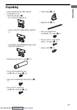
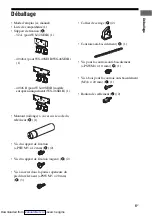
Page 5: ...0SE1B Europe model only WS 46SE1B 1 Extension neck for TV stand B 1 Screw for attachment bracket PSW M5 12 mm C 2 Screw for attachment bracket Silver D 2 Screw for TV stand head PSW M5 20 mm E 3 Cable clamp F 2 Support belt G 1 Screw for support belt PSW M4 10 mm H 1 Wood screw for support belt M3 8 20 mm I 1 Anchor bolt J 2 Downloaded from ManualsNet com search engine ...

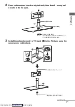
Page 6: ...ith TV only This speaker attachment bracket cannot be used with the SU FL71M SU FL71L floor stand If you want to hang the SA 32SE1 SA 40SE1 SA 46SE1 TV Sound Bar System hang it directly on the wall 1 Remove the screws from the TV stand then detach the TV from the TV stand Installing the TV Sound Bar System on the TV stand The screws at the TV stand Downloaded from ManualsNet com search engine ...

Page 7: ... extension neck for TV stand B to the TV stand using the screws removed in step 2 Stand base Screws for the stand The 32 inch and 40 inch model 2 screws The 46 inch model 3 screws Original neck 1 2 1 2 B The screw removed in step 2 B The screws removed in step 2 1 2 continued Downloaded from ManualsNet com search engine ...

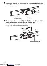
Page 8: ...t bracket A to the TV Sound Bar System with the screw for attachment bracket PSW M5 12 mm C Check the engraving on the rear of the attachment bracket and use a suitable bracket for the TV For details refer to the supplied Compatible list TV Sound Bar System Rear cover C A Downloaded from ManualsNet com search engine ...

Page 9: ...ttachment bracket Silver D Be sure to fasten the screws to the screw holes pointed with mark Notes After installation the screw for attachment bracket Silver will protrude from the screw hole This is not a malfunction When carrying the TV Sound Bar System installed TV do not hold it by the TV Sound Bar System Doing so may cause damage or injury The screws at the rear of the TV Cloth D continued Do...

Page 10: ...TV instead of the TV Sound Bar System 9 Secure the TV to the TV stand with the screw for TV stand head PSW M5 20 mm E 10After you have made all connections you can use the cable clamp F to neatly secure the cables Note As a protective measure secure the TV For details see Preventing the TV from toppling over x 3 E Downloaded from ManualsNet com search engine ...

Page 11: ...the TV after allowing for a space of less than 25 cm 9 7 8 in from the wall The wall will prevent the TV from falling even if the TV leans backward towards the wall When installing the TV on a rack 1 Place the TV on the center of the rack 2 Fit the support belt G to the TV stand then firmly fasten with the screw for support belt PSW M4 10 mm H using a screw driver 3 Fasten the support belt to the ...

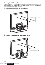
Page 12: ...he wall Secure the fastener to a reinforced wall Even if you have secured the TV to the rack be sure to secure it to a wall by following this procedure 1 Remove the screws from the rear of the TV 2 Fasten the anchor bolt J to the rear of the TV The screws at the rear of the TV J Downloaded from ManualsNet com search engine ...

Page 13: ...ing or chain through the holes of the anchor bolt and the fastener 2 Firmly tie both ends of the string or chain together Adjusting the angle of the TV Less than 25 cm 9 7 8 in Less than 25 cm 9 7 8 in TV installed on the floor TV installed on a rack 1 2 0 6 Downloaded from ManualsNet com search engine ...

Page 14: ...1 4 in 9 in 1 7 16 in Mass approx 1 3 kg 2 lb 14 oz Attachment bracket 40 46 B Europe model only Dimensions w h d approx 332 mm 232 mm 35 mm 13 1 8 in 9 1 4 in 1 7 16 in Mass approx 1 3 kg 2 lb 14 oz Extension neck for TV stand Dimensions approx φ 43 mm 216 8 mm φ 1 3 4 in 8 5 8 in Mass approx 0 66 kg 1 lb 8 oz Design and specifications are subject to change without notice Downloaded from ManualsN...

Page 15: ...Downloaded from ManualsNet com search engine ...

Page 16: ... basculement ou la chute de l appareil Veillez à observer les consignes de sécurité préconisées pour éviter de tels accidents Le non respect des consignes suivantes peut être fatal ou entraîner des blessures graves en provoquant un incendie ou une électrocution ou encore le basculement ou la chute de l appareil Pour éviter tout risque de chute des produits installez les à un endroit sûr où ils ne ...

Page 17: ...oduits et de provoquer des blessures Le non respect des consignes suivantes peut entraîner des blessures ou des dommages matériels N installez aucun équipement autre que ceux indiqués Le support de fixation d enceinte WS 32SE1B WS 40SE1B WS 46SE1B est conçu pour être utilisé exclusivement avec l équipement spécifié Si vous installez un équipement autre que ceux mentionnés il peut tomber ou se bris...

Page 18: ...s mains ou les doigts au cours du montage des produits Remarques sur le nettoyage Nettoyez les produits avec un chiffon doux légèrement humidifié à l aide d un détergent non agressif N utilisez pas de tampons abrasifs de poudres à récurer ou de solvants tels que du diluant du benzène ou de l alcool Si vous avez des questions ou en cas de problème concernant ce produit veuillez vous adresser à votr...

Page 19: ...isser sur le socle du téléviseur B 1 Vis du support de fixation PSW M5 12 mm C 2 Vis du support de fixation argent D 2 Vis à insérer dans la partie supérieure du pied du téléviseur PSW M5 20 mm E 3 Collier de serrage F 2 Courroie anti basculement G 1 Vis pour la courroie anti basculement PSW M4 10 mm H 1 Vis à bois pour la courroie anti basculement M3 8 20 mm I 1 Boulon de scellement J 2 Downloade...

Page 20: ...ette bride de fixation de haut parleur ne peut être utilisée avec le support au sol SU FL71M SU FL71L Si vous souhaitez suspendre le système de barre de son pour téléviseur SA 32SE1 SA 40SE1 SA 46SE1 TV fixez le directement sur le mur 1 Retirez les vis servant à fixer le pied au téléviseur puis démontez le pied du téléviseur Installation de la barre de son sur le pied du téléviseur Vis de fixation...

Page 21: ... montant fourni en guise de rallonge B au socle du téléviseur à l aide des vis retirées à l étape 2 Socle Vis de fixation du socle Modèle 82 et 102 cm 2 vis Modèle 117 cm 3 vis Montant d origine 1 2 1 2 B Vis retirée à l étape 2 B Vis retirées à l étape 2 1 2 suite Downloaded from ManualsNet com search engine ...

Page 22: ... de son à l aide des vis prévues à cet effet PSW M5 12 mm C Vérifiez l inscription gravée au dos du support de fixation afin d utiliser un support adapté à votre téléviseur Pour plus d informations à ce sujet reportez vous à la liste de compatibilité fournie Barre de son pour téléviseur Couvercle arrière C A Downloaded from ManualsNet com search engine ...

Page 23: ...rez les vis dans les trous de montage indiqués par le repère Remarques Une fois la barre de son installée les vis du support de fixation argent dépassent des trous de montage Cela est tout à fait normal Évitez de saisir le téléviseur par la barre de son lorsque vous avez besoin de le déplacer Vous risqueriez en effet de vous blesser ou d endommager le matériel Vis au dos du téléviseur Tissu D suit...

Page 24: ...installez sur son pied 9 Fixez le téléviseur sur la partie supérieure du pied à l aide des vis prévues à cet effet PSW M5 20 mm E 10Une fois tous les branchements effectués servez vous du collier de serrage F pour maintenir les câbles en place Remarque Par mesure de sécurité veillez à garantir une parfaite stabilité de votre installation Pour plus de détails reportez vous à la section Système anti...

Page 25: ... l installation du téléviseur sur le meuble Prévoyez un espace maximum de 25 cm 9 7 8 pouces entre le téléviseur et le mur Si le téléviseur venait à basculer vers l arrière le mur l empêcherait de tomber Installation du téléviseur sur un meuble 1 Placez le téléviseur au centre du meuble 2 Fixez la courroie anti basculement G sur le socle du téléviseur puis serrez la vis prévue à cet effet PSW M4 1...

Page 26: ... au mur Installez l attache sur un mur renforcé Même si vous avez sécurisé le téléviseur sur le meuble veuillez le rattacher au mur en procédant comme indiqué ci dessous 1 Enlevez les vis au dos du téléviseur 2 Vissez le boulon de scellement J à l arrière du téléviseur Vis au dos du téléviseur J Downloaded from ManualsNet com search engine ...

Page 27: ...spectifs du boulon de scellement et de l attache murale 2 Reliez les deux extrémités du lien par un nœud solide En ajustant l angle du téléviseur Moins de 25 cm 9 7 8 pouces Moins de 25 cm 9 7 8 pouces Téléviseur installé à même le sol Téléviseur installé sur un meuble 1 2 0 6 Downloaded from ManualsNet com search engine ...

Page 28: ...iron 1 3 kg 2 livres 14 onces Support de fixation 40 46 B modèle européen uniquement Dimensions l h p environ 332 mm 232 mm 35 mm 13 1 8 pouces 9 1 4 pouces 1 7 16 pouces Poids environ 1 3 kg 2 livres 14 onces Montant rallonge à visser sur le socle du téléviseur Dimensions environ φ 43 mm 216 8 mm φ 1 3 4 pouces 8 5 8 pouces Poids environ 0 66 kg 1 livres 8 onces La conception et les spécification...

Page 29: ...Downloaded from ManualsNet com search engine ...

Page 30: ...scarga o al volcarse o caerse el producto Para evitar tales accidentes asegúrese de cumplir las precauciones de seguridad Si no se tienen en cuenta las precauciones siguientes pueden producirse lesiones graves o incluso la muerte a raíz de un incendio o una descarga eléctrica o el producto puede volcarse No deje caer los productos ni los instale en ningún lugar donde puedan caerse Asegúrese de con...

Page 31: ...e ventilación con un paño etc el sistema podría sobrecalentarse y provocar un incendio Tenga cuidado de no tropezar con los cables Si tropezara los productos podrían volcarse y provocar lesiones Si no se tienen en cuenta las precauciones siguientes se pueden producir lesiones graves o daños en la propiedad No instale equipos que no sean el producto especificado El soporte de fijación de altavoz WS...

Page 32: ...ctos Una persona sola puede sufrir accidentes o lesiones Durante el proceso procure mantener alejados a los niños Asegúrese de seguir las instrucciones para instalar firmemente los productos Apriete firmemente los tornillos Si no instala el Sistema de barra de sonido de televisor adecuadamente puede caerse y provocar daños o lesiones Tenga cuidado de no pillarse los dedos ni las manos al montar lo...

Page 33: ...uración 7 Instalación del Sistema de barra de sonido de televisor en el soporte de televisor 7 Cómo evitar la caída del televisor 12 Ajuste del ángulo del televisor 14 Especificaciones 15 Downloaded from ManualsNet com search engine ...

Page 34: ...B 1 Cuello de extensión para el soporte de televisor B 1 Tornillo para el soporte de fijación PSW M5 12 mm C 2 Tornillo para el soporte de fijación plateado D 2 Tornillo para la cabeza del soporte de televisor PSW M5 20 mm E 3 Abrazadera para cables F 2 Cinta de sujeción G 1 Tornillo para la cinta de sujeción PSW M4 10 mm H 1 Tornillo de madera para la cinta de sujeción M3 8 20 mm I 1 Perno de anc...

Page 35: ...r Este soporte de fijación de altavoz no se puede utilizar con el soporte de suelo SU FL71M SU FL71L Si desea colgar el Sistema de barra de sonido de televisor SA 32SE1 SA 40SE1 SA 46SE1 cuélguelo directamente sobre la pared 1 Extraiga los tornillos del soporte de televisor y a continuación separe el televisor del soporte de televisor Instalación del Sistema de barra de sonido de televisor en el s...

Page 36: ...el soporte de televisor B en el soporte de televisor con los tornillos extraídos en el paso 2 Base del soporte Tornillos del soporte Modelos de 32 pulgadas y 40 pulgadas 2 tornillos Modelo de 46 pulgadas 3 tornillos Cuello original 1 2 1 2 B Tornillo extraído en el paso 2 B Tornillos extraídos en el paso 2 1 2 Downloaded from ManualsNet com search engine ...

Page 37: ...ra de sonido de televisor con el tornillo para el soporte de fijación PSW M5 12 mm C Compruebe el grabado de la parte posterior del soporte de fijación y utilice el soporte adecuado para el televisor Para obtener más información consulte la Lista de dispositivos compatibles suministrada Sistema de barra de sonido de televisor Cubierta posterior C A continúa Downloaded from ManualsNet com search en...

Page 38: ...te de fijación plateado D Asegúrese de fijar los tornillos en los orificios que presentan la marca Notas Tras la instalación el tornillo para el soporte de fijación plateado sobresaldrá del orificio No se trata de un fallo de funcionamiento Durante el transporte del televisor instalado en el Sistema de barra de sonido de televisor no lo coja por el Sistema de barra de sonido de televisor ya que po...

Page 39: ...Sistema de barra de sonido de televisor 9 Fije el televisor en el soporte de televisor con el tornillo para la cabeza del soporte de televisor PSW M5 20 mm E 10Una vez realizadas todas las conexiones podrá utilizar la abrazadera para cables F para fijar correctamente todos los cables Nota Como medida de seguridad fije el televisor Para obtener más información consulte Cómo evitar la caída del tele...

Page 40: ...as dejar una distancia de al menos 25 cm 9 7 8 pulg de la pared La pared evitará que el televisor se caiga incluso si se inclina hacia atrás hacia la pared Cuando instale el televisor en el estante 1 Coloque el televisor en el centro del estante 2 Coloque la cinta de sujeción G en el soporte de televisor y a continuación fíjela firmemente con el tornillo para la cinta de sujeción PSW M4 10 mm H co...

Page 41: ...red Fije el sujetador en una pared reforzada Incluso si ha fijado el televisor al estante asegúrese de fijarlo en una pared mediante este procedimiento 1 Extraiga los tornillos de la parte posterior del televisor 2 Fije el perno de anclaje J en la parte posterior del televisor Tornillos de la parte posterior del televisor J continúa Downloaded from ManualsNet com search engine ...

Page 42: ... agujeros del perno de anclaje y el sujetador 2 Ajuste ambos extremos de la cuerda o la cadena simultáneamente Ajuste del ángulo del televisor Menos de 25 cm 9 7 8 pulg Menos de 25 cm 9 7 8 pulg Televisor instalado en el suelo Televisor instalado en un estante 1 2 0 6 Downloaded from ManualsNet com search engine ...

Page 43: ...pulg 1 7 16 pulg Peso aprox 1 3 kg 2 lb 14 oz Soporte de fijación 40 46 B solo el modelo de Europa Dimensiones an al prf aprox 332 mm 232 mm 35 mm 13 1 8 pulg 9 1 4 pulg 1 7 16 pulg Peso aprox 1 3 kg 2 lb 14 oz Cuello de extensión para el soporte de televisor Dimensiones aprox φ 43 mm 216 8 mm φ 1 3 4 pulg 8 5 8 pulg Peso aprox 0 66 kg 1 lb 8 oz El diseño y las especificaciones están sujetos a cam...

Page 44: ...Sony Corporation Printed in Malaysia 1 Downloaded from ManualsNet com search engine ...

Reviews: