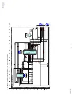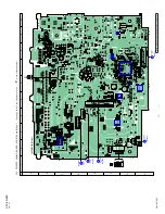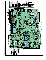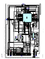
XAV-60/E60
17
SECTION 4
ELECTRICAL ADJUSTMENTS
MONITOR SECTION
If any of the following parts was replaced, execute the “V-COM
Adjustment” and “Flicker Adjustment” as mentioned below.
•
Complete AUDIO board
•
AUDIO board: IC504
•
Complete VISUAL board
•
VISUAL board: IC2001
•
Liquid crystal display panel (LCD1401)
•
Complete LCD board
1. SETTINGS
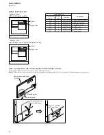
1-1. Tools and measuring devices for adjustment
Tools and measuring devices
Item used
PC
(The one with serial port. The USB-
RS232C conversion is available.)
V-COM adjustment and
Flicker adjustment
Communication software
(Hyper Terminal etc.)
Serial cable for RS232C
(Cross cable)
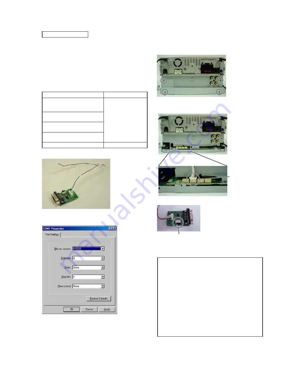
RS232C-JIG OVERALL ASSY
(Part No. A-1777-380-A)
Oscilloscope
V-COM adjustment
RS232C-JIG OVERALL ASSY
1-2. Serial port setting
Please setting it as follows.
1-3. Connection with set
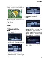
Procedure:
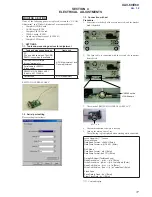
1. Four screws in the back of the set are removed, and the bracket
back is detached.
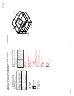
2. The 5pin cable is connected with the second the connector
from the left.
CN2002 on the
VISUAL board
3. The switch of RS232C-JIG OVERALL ASSY is “L”.
H
m o
L
4. The communication software is start up.
5. Turn on the main power of set.
The following log is displayed when starting while connected.
xxxxx Visual Ver[**** ] xxxxx
Techwell Mode
Data Read Format : ‘r 005A’+ [Enter]
Data Write Format: ‘w 01C4 03’+ [Enter]
DAC Mode
Data Read Format : ‘dr0’+ [Enter]
Data Write Format: ‘dw1 7D’+ [Enter]
Gerda WB Adjust (TestMode5 only)
Read Drive Value : ‘grd’+’r / g / b’ [Enter]
Write Drive Value : ‘gwd’+’r / g / b’+’value(hex)’ [Enter]
Read CutOff Value : ‘grc’+’r / g / b’ [Enter]
Write CutOff Value : ‘gwc’+’r / g / b’+’value(hex)’ [Enter]
Flash Write
Save Data to Flash : ‘ds’+ [Enter]
Clear Flash Data : ‘dc’+ [Enter]
****: Version display
Ver. 1.2
Summary of Contents for XAV-60 - 6.1 Inch Avc
Page 92: ...92 XAV 60 E60 MEMO ...


