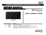
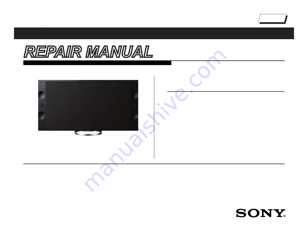
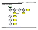
background image

REPAIR MANUAL

Self Diagnosis

Supported model

HISTORY INFORMATION FOR THE FOLLOWING MANUAL:

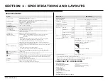
LCD Digital Color TV

9-883-510-04

RB1FS 

Chassis


Segment: FS-M

Version Date 

Subject

1.0  

03/29/2013 

Original Manual Release Date.

2.0 

07/03/2013 

Updated Section 3 - Repair Information. Reissue entire manual.

3.0 

10/25/2013 

Updated Section 4 - Exploded View/Part Number Information. Replaced pages 22 - 28.

4.0 

12/20/2013 

Updated Section 3 - Repair Information. Added pages 18 - 22.


Updated Section 4 - Exploded View/Part Number Information. Replaced pages 29 and 33.

     MODEL 

           COMMANDER               DESTINATION

XBR-65X900A 

  RM-YD087/RMF-YD001 

US/CND


XBR-65X900A

Summary of Contents for XBR-65X900A

Page 1: ...lease Date 2 0 07 03 2013 Updated Section 3 Repair Information Reissue entire manual 3 0 10 25 2013 Updated Section 4 Exploded View Part Number Information Replaced pages 22 28 4 0 12 20 2013 Updated Section 3 Repair Information Added pages 18 22 Updated Section 4 Exploded View Part Number Information Replaced pages 29 and 33 MODEL COMMANDER DESTINATION XBR 65X900A RM YD087 RMF YD001 US CND XBR 65...

Page 2: ... 3D Viewing 13 Section 3 Repair Information 14 Repairing the TV 14 Removing the Table Top Stand and Cover Under 14 Removing the Rear Cover 14 Replacing the Main Board 15 Replacing the Power Supply Board 18 Replacing the TCON Board 18 Replacing the CX Board 22 Replacing the Switch Unit 24 Removing the Woofer Speaker 24 Removing the WLAN Module and HW Board 24 Removing the Side Speakers 25 Removing ...

Page 3: ... CAUTIONS AND WARNINGS ATTENTION Ces instructions de service sont à l usage du personnel de service qualifié seulement Pour prévenir le risque de choc électrique ne pas faire l entretien autre que celui contenu dans le Mode d emploi à moins que vous soyez qualifié faire ainsi ALERTE Afin d eviter tout risque d electrocution provenant d un chássis sous tension un transformateur d isolement doit etr...

Page 4: ...eakage as described in Leakage Test LEAKAGE TEST The AC leakage from any exposed metal part to earth ground and from all exposed metal parts to any exposed metal part having a return to chassis must not exceed 0 5 mA 500 microamperes Leakage current can be measured by any one of three methods 1 A commercial leakage tester Follow the manufacturers instructions provided with the tester 2 A battery o...

Page 5: ...nual for supported formats USB DLNA RS232C Serial Control mini jack IR IN mini jack REMOTE These jacks are for receiving the external control signal LCD Liquid Crystal Display Panel 12 5 W 12 5 W 20 W 20W Video Audio input phono jacks 75 ohm external terminal for RF inputs Stereo mini jack NTSC American TV standard SECTION 1 SPECIFICATIONS AND LAYOUTS Screen size dimensions and mass are approximat...

Page 6: ...ule POWER BOARD NETWORK WLAN MODULE ASSEMBLY HW Board WLAN Module POWER BOARD E LD TS BOARD MAIN BOARD BAFS BAF2S POWER SUPPLY BOARD G8 SWITCH UNIT CX CX2 BOARD POWER SUPPLY BOARD G6 TCON POWER BOARD NETWORK BOARD LAYOUT XBR 65X900A CX CX2 only included in models with BAFS Board Serial No 1800001 6010000 ...

Page 7: ...XBR 65X900A 3 SECTION 1 SPECIFICATIONS AND LAYOUTS WIRE DRESSING XBR 65X900A SMART CORE BLOCK CX CX2 Board wire only included in models with BAFS Board Serial No 1800001 6010000 ...

Page 8: ...ISPLAY Channel 5 Volume POWER NOTE This differs from accessing Service Adjustments Mode Volume SECTION 2 TROUBLESHOOTING SelfDiagnosis Supported model SELF CHECK 000 RESERVED 00 000 RESERVED 00 002 MAIN_POWE 00 003 DC_ALERT 00 003 AUD_PROT 00 003 HDMI_EQ 00 003 TU_DEMOD 00 004 VLED 00 004 LD_ERR 00 005 HFR_ERR 00 005 TCON_ERR 120123132522 120123113645 02 005 P_ID ERR 00 006 BACKLITE 00 007 TEMP_ER...

Page 9: ...ower Audio 2X 3X 4X 5X 6X 7X 8X No WIFI Dead set No Video Whole Screen Distortion Isolated Area Distortion No Audio MAIN BOARD POWER SUPPLY LCD Panel TCON SERVICE BULLETIN SOFWARE UPDATE WLAN Video Protection Modes 4 Follow the associated flowcharts in the Training Manual to isolate the board Board Immediate Shutdown After Power ON 7X NOTE REFER TO LCD PANELS SERVICE MANUAL IN REFERENCE LIBRARY DA...

Page 10: ...2 CVBS COMP VIDEO 1 CVBS RF HDMI 1 LCD PANEL HFR TCON L R OPTICAL AUDIO OUT HDMI 3 TUNER ETHERNET USB2 0 HDMI 2 LVDS AC IN USB HUB LED DRIVE LD L R USB2 0 MAIN BOARD IC9001 HP LINE OUT HDMI SWITCH EQ USB3 0 BAFS G8 G6 BLUETOOTH HSF HIF WIFI SMART CORE SWITCH UNIT TS A V DECODER VIDEO PROCESS SUB WOOFER AMP HDMI 4 CX CX2 AMP HW HUS IC9000 LVDS ...

Page 11: ...VIDEO 1 CVBS RF HDMI 1 LCD PANEL HFR TCON L R OPTICAL AUDIO OUT HDMI 3 TUNER ETHERNET USB2 0 HDMI 2 LVDS AC IN USB HUB LED DRIVE LD L R USB2 0 MAIN BOARD IC9001 HP LINE OUT HDMI SWITCH EQ USB3 0 BAF2S G8 G6 BLUETOOTH HSF HIF WIFI SMART CORE SWITCH UNIT TS A V DECODER VIDEO PROCESS SUB WOOFER AMP AMP HW HUS IC9000 LVDS HDMI 4 HDMI EQ ...

Page 12: ...D DIGITAL_STBY CN6601 2 5 AU_GND 24 25 TCON_12V 28 STBY3 3V TCON_GND AC_OFF_DET BL_ERR 3 DIGITAL_STBY REG_12V 26 27 GND REG 12V 5 6 5 6 CN9101 BAFS BAF2S G8 MAIN POWER AND CONVERTER MAIN BOARD PFC PRI_VCC AND STANDBY POWER SUPPLY 6 SENSE GND BL_ON 6 11 GND 12 17 18 20 21 23 TCON_ON STBY GND POWER_ON CN4803 20 5 4 TCON_12V 1 STBY3 3V AC_OFF_DET BL_ERR DIGITAL_STBY REG_12V 3 2 BL_ON 6 8 GND 18 12 14...

Page 13: ...ng No Yes No See Stanby LED Blinking Flowchart Yes Does red Standby LED on front panel light High 2 5V on Pin 1 of CN6101 on Power Supply Yes No Main Board Press power button while monitoring Pin 7 of CN6601 on Power Supply Board High 3 3V appears momentarily Yes No Power Supply Board Power Supply Board Power Supply Board Remove AC power and wait at least 30 seconds before reapplying ...

Page 14: ...Information on page 27 STANDBY LED BLINKING FLOWCHART Protect Shutdown Standby LED Blinking No Yes Power Supply Board No Yes 2X Main Board 3X 4X No Yes 5X Yes 6X No 7X Immediately LCD Panel TCON LCD Panel Yes No After a while Check ventilation 10X HEM3 Board 8X See Triage Chart Main Board Power Supply Board No Yes ...

Page 15: ...DEO FLOWCHART No Video Backlights turned on Unplug LVDS connector with unit off Turn unit back on Test patterns display on screen Yes No TCON LCD Panel Sony logo appears momentarily No Main Board No Yes Yes Main Board Locate CN6401 on Power Supply Board Zero volts at Pin 5 TCON LCD Panel Yes No Zero volts at Pin 3 Yes Main Board No LCD Panel ...

Page 16: ...ION FLOWCHART Video Distortion Is distortion across entire screen Any horizontal lines No No Yes Yes Improper or missing colors Yes Main Board No Vertical lines or bars No Yes Lines move when wide mode changed Yes No TCON LCD Panel Main Board LCD Panel Any single or isolated vertical lines Yes LCD Panel More than 1 vertical band No Yes TCON LCD Panel ...

Page 17: ...reen Yes Main Board No Press 3D button on Remote Commander and select Simulated 3D Passive 3D Glasses View image with Passive 3D Glasses Double images become one Yes 3D OK No 3D Not Working For Part Number information refer to Section 4 Exploded View Part Number Information on page 27 ...

Page 18: ... the repair resolved the issue REMOVING THE TABLE TOP STAND AND COVER UNDER 1 Place TV face down on a soft and flat surface 2 Grasp Cover Under as shown then carefully pull upwards to release the locking clips and lift to detach 3 Remove 4 screws from Table Top Stand and pull down as shown to detach from Rear Cover REMOVING THE REAR COVER 1 Remove 1 screw from AC Cover and disconnect the AC Power ...

Page 19: ...ck locking bar to reconnect the FFC Cable and secure the connector 7 Reconnect remaining connectors REPLACING THE MAIN BOARD The Main Board used in this model is available for repair For Part Number information refer to Section 4 Exploded View Part Number Information on page 27 1 Disconnect LVDS and FFC cables a Press down the 2 locking clips and pull LVDS cables to release b Lift the black lockin...

Page 20: ...nation Data Value is selected it may corrupt the Sofware requiring a Main Board replacement 12 Select the correct destination of the TV press 3 to increase or 6 to decrease the data value Use the table below for reference Model Name Destination Data Value XBR 65X900A US CND ATSC UC_BASE 13 Press MUTING then 0 to save the changes DIGITAL SERVICE 002 MODEL 001 DEST WRITE ATSC UC_BASE 14 Press 1 unti...

Page 21: ...screen and re enter the correct number 22 Press to save the Serial Number DIGITAL MODEL SERVICE SerialNumberEdit 1 SerialNumber 1800001 WRITE 23 Clear the Self Check screen a Press POWER to exit Service Mode b Press the following buttons on the Remote Commander within 1 second of each other DISPLAY Channel 5 Volume POWER SELF CHECK 000 RESERVED 00 000 RESERVED 00 002 MAIN_POWE 00 003 DC_ALERT 00 0...

Page 22: ...e TV c Wait until the Software update is complete and TV turns OFF REPLACING THE TCON BOARD The TCON Board used in this model is available for repair For Part Number information refer to Section 3 Repair Information on page 14 1 Locate and disconnect all connectors from the TCON Board 2 Lift the black locking bar and pull LVDS cables to release 3 Remove 6 screws from TCON Shield Case and lift as s...

Page 23: ...s used Smart Core amber and green LED will remain blinking and Software can not update c If valid file found below message will appear NOTE TV will reboot minutes after the USB device is inserted then the red LED lits and the amber LED blinks 9 When the Software update is completed expect one of the following a The Smart Core LED will change to white blinking and TV goes to Standby mode Turn ON TV...

Page 24: ...0 19 Press 3 to increase the data value from 0 to 1 VPC SERVICE 005 001 PANEL BU_NVM 1 20 Wait until process is completed and the value changes to 2 or 3 VPC SERVICE 005 001 PANEL BU_NVM 3 21 Press OPTION to select the Digital Service menu Verify the Software version Model ID and Product ID are correct BT SCF 20 01 SYF Model ID Software Version Product ID DIGITAL SERVICE 001 OP 000 VERS MAIN EXT D...

Page 25: ...FSM FSL_BASE DVB LTN_BASE GAA CO1 XBR 55X907A 18535110 070DC8A1 05060040 T550QVD02 0 FSM FSL_BASE DVB LTN_BASE GAA CO1 XBR 65X850A 18586300 0F4D18B1 01062040 UD3Y650LN0101 FB_BASE ATSC UC_BASE AAA U2 XBR 65X850A 18586301 0F4D18B1 01062040 UD3Y650LN0101 FB_BASE ATSC UC_BASE AAA CA2 XBR 65X850A 18586302 074D18B1 03062040 UD3Y650LN0101 FB_BASE ATSC LTN_BASE AAA LA1 XBR 65X900A 18521100 0F0D18A0 01060...

Page 26: ...lease refer to step f e Wait approximately 5 minutes until the Software installation is completed and a successful update message appears CAUTION TV will turn ON and OFF during this process f After removing the USB device press POWER to turn TV OFF 2 Remove 2 screws and disconnect connector from CX Board to detach 3 Replace the CX Board with the new CX2 Board install screws and connector 4 Access ...

Page 27: ...n Display graphics appear wait 10 seconds and cycle AC Power again 15 TV turns ON with normal OSD 16 Prepare TV to install the Software again Since the TV already has the latest Software installed it must be forced to install the latest version a Press POWER to turn OFF the TV b Access Service Mode by pressing the following buttons within 1 second of each other DISPLAY Channel 5 Volume POWER 17 Pr...

Page 28: ...sconnect 2 connectors from the Switch Unit then remove 2 screws and lift to detach 2 Install the new Switch Unit screws and connectors REMOVING THE WOOFER SPEAKER 1 Disconnect connector from Woofer Speaker remove 5 screws and lift to detach 2 Refer to these instructions to remove the opposite Woofer Speaker REMOVING THE WLAN MODULE AND HW BOARD 1 Disconnect connector remove 2 screws and lift to de...

Page 29: ...Speaker 80MM to detach Release 2 locking clips to remove Speaker Bracket and lift Speaker Ornament to detach Speaker 80MM Speaker 80MM Speaker Bracket Speaker Bracket Speaker Ornament Speaker Ornament 5 Remove 2 screws from Speaker 18MM and lift to detach Speaker 18MM Speaker 18MM 6 Remove 2 screws from TW Bracket and lift to detach TW Bracket TW Bracket 7 Lift Loud Speaker to detach Release 2 loc...

Page 30: ... release 3 Unclamp 2 side locking clips from Lid SC and lift to detach Lid SC Lid SC 4 Release the HSF Board connector from the locking clip to disconnect it and lift to detach Then disconnect and remove HSF Board FPC BT and Bluetooth Module HSF Board HSF Board Bluetooth Module Bluetooth Module FPC BT FPC BT 5 Locate HIF Board and slide upwards to detach HIF Board HIF Board REMOVING THE TS BOARD 1...

Page 31: ...s of the diagram NOTE The components identified by shading and mark are critical for safety Replace only with part number specified NOTE The components identified by a red outline and a mark contain confidential information Specific instructions must be adhered to whenever these components are repaired and or replaced See Appendix A SECTION 4 EXPLODED VIEW PART NUMBER INFORMATION TABLE TOP STAND 1...

Page 32: ... 4 457 576 01 LABEL UNDER TERMINAL FOR SERIAL No 1800001 6010000 ONLY 54 4 449 086 41 LABEL UNDER TERMINAL FOR SERIAL No 6010001 6710000 ONLY 55 4 449 005 01 LABEL REAR TERMINAL 56 4 454 666 03 COVER UNDER 57 4 299 531 01 AC COVER 58 1 839 679 12 POWER SUPPLY CORD 59 1 474 516 11 G6 BOARD COMPLETE 60 4 298 004 01 SPACER B 61 1 474 518 11 G8 BOARD COMPLETE 62 A 1938 830 A BAFS BOARD COMPLETE FOR SE...

Page 33: ...UPDATE THE SOFTWARE TO THE LATEST VERSION 102 A 1952 947 A CX2 BOARD MOUNTED FOR MODELS WITH BAFS BOARD ONLY PLEASE CONFIRM THE INFORMATION ON THE ORIGINAL BOARD LABEL BEFORE ORDERING THIS PART AFTER REPLACING THE CX2 BOARD YOU MUST UPDATE THE SOFTWARE TO THE LATEST VERSION 103 1 492 349 11 SWITCH UNIT 104 4 457 451 01 SHEET THERMAL 105 1 895 396 11 TCON BOARD COMPLETE AFTER REPLACING THE TCON BOA...

Page 34: ... 154 153 158 156 155 157 157 156 154 158 151 4 454 657 01 COVER SP LEFT ORDER THIS PART WHEN REPLACING THE LCD PANEL 152 1 895 387 11 PWB BOARD MOUNTED NETWORK 153 1 858 894 11 LOUD SPEAKER 80MM 154 4 478 227 01 BRACKET SP ORDER THIS PART WHEN REPLACING THE LCD PANEL 155 4 454 664 01 ORNAMENT SP 156 1 858 893 11 LOUD SPEAKER 18MM 157 4 454 659 01 BRACKET TW ORDER THIS PART WHEN REPLACING THE LCD P...

Page 35: ...nfidential information Specific instructions must be adhered to whenever these components are repaired and or replaced See Appendix A 206 205 204 202 201 203 SMART CORE BLOCK 201 4 463 080 01 LID SC 202 A 1936 360 A HIF BOARD MOUNTED 203 1 846 688 11 FPC BT ORDER THIS PART WHEN REPLACING BLUETOOH MODULE OR HSF LM BOARD 204 A 1936 358 A HSF LM BOARD MOUNTED 205 1 492 062 11 BLUETOOTH MODULE 206 4 4...

Page 36: ...x A CONNECTORS REF NO PART NO DESCRIPTION 255 254 252 251 256 257 258 259 253 REF NO PART NO DESCRIPTION 251 1 846 696 11 LEAD WIRE WITH CONNECTOR 51P FOR SERIAL No 1800001 6610000 ONLY 252 1 910 107 84 CONNECTOR ASSEMBLY 3P BAF TS 253 1 910 107 82 LVDS FLEXIBLE FLAT CABLE 20P 254 1 846 700 11 LVDS FLEXIBLE FLAT CABLE 51P 255 1 846 701 11 LVDS FLEXIBLE FLAT CABLE 41P 260 256 1 910 107 80 HARNESS A...

Page 37: ...8 126 02 SCREW PSW M3X6 STEP 4 457 815 02 4 256 393 01 P N DESCRIPTION XBR 65X900A Rear Cover 25 Rear Cover 4 Rear Cover 2 Loud Speakers 18MM 4 Smart Core Block 1 Bracket Module 2 CX Board 2 Switch Unit 2 Main Board 13 Bracket HUS 2 TS Board 1 TW Brackets 4 Mounted PWBs 4 Power Supply Board G8 5 Power Supply Board G6 5 TCON Shield to Panel 6 Speaker Cover Right 12 Speaker Cover Left 12 4 159 298 0...

Page 38: ...STALLATION MISCELLANEOUS PART NO DESCRIPTION 4 273 074 14 FLYER SAFETY 4 463 174 01 BADGE XBR LOGO H6 4 462 315 01 SCREW CAP 4 262 708 04 CLAMPER CABLE 4 441 738 01 CLAMPER CABLE L 4 096 737 01 CUSHION G 4 454 669 01 PANEL ORNAMENT SC 7 600 031 96 TAPE 3M 1350FW 1 15MMX66M WHT 7 600 031 97 TAPE 3M 1350FB 1 15MMX66M BLK 4 465 860 01 TAPE_95 OPTIONAL ACCESSORIES PART NO DESCRIPTION 4 443 737 02 SUPP...

Page 39: ...ey components shall be identified with a red outline and a 2 Only repair boards or components listed in the service manual shall be utilized for replacement and or repair 3 Disassembly decryption or reverse engineering component s is strictly prohibited 4 Any board in which the Servicer replaces an encryption key component must be placed back into the set it orignally came from and the replaced de...

Reviews: