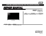
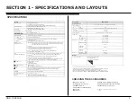
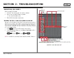
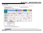
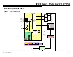
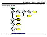
background image

REPAIR MANUAL

Self Diagnosis

Supported model

HISTORY INFORMATION FOR THE FOLLOWING MANUAL:

LCD Digital Color TV

9-888-607-01

RB2T 

Chassis


Segment: HA

Version Date 

Subject

1.0  

04/28/2014 

Original Manual Release Date.

   MODEL 

           COMMANDER             

DESTINATION

XBR-70X850B          RM-YD102 /RMF-YD003  

  US/CND

XBR-70X850B

Summary of Contents for XBR-70X850B

Page 1: ...HISTORY INFORMATION FOR THE FOLLOWING MANUAL LCD Digital Color TV 9 888 607 01 RB2T Chassis Segment HA Version Date Subject 1 0 04 28 2014 Original Manual Release Date MODEL COMMANDER DESTINATION XBR 70X850B RM YD102 RMF YD003 US CND XBR 70X850B ...

Page 2: ...t 10 Video Distortion Flowchart 11 No 3D Viewing 12 Section 3 Repair Information 13 Repairing the TV 13 Removing the Camera Module and Table Top Stand 13 Removing the Rear Cover 13 Replacing the Main Board and Tuner Board 14 Replacing the Power Supply Board 17 Replacing the Switch Unit 18 Removing the USB Assembly 18 Removing the Speakers 18 Removing the Smart Core Block 19 Section 4 Exploded View...

Page 3: ...INGS ATTENTION Ces instructions de service sont à l usage du personnel de service qualifié seulement Pour prévenir le risque de choc électrique ne pas faire l entretien autre que celui contenu dans le Mode d emploi à moins que vous soyez qualifié faire ainsi ALERTE Afin d eviter tout risque d electrocution provenant d un chássis sous tension un transformateur d isolement doit etre utilisé lors de ...

Page 4: ...eakage as described in Leakage Test LEAKAGE TEST The AC leakage from any exposed metal part to earth ground and from all exposed metal parts to any exposed metal part having a return to chassis must not exceed 0 5 mA 500 microamperes Leakage current can be measured by any one of three methods 1 A commercial leakage tester Follow the manufacturers instructions provided with the tester 2 A battery o...

Page 5: ...not guaranteed for this TV Operating temperature REMOTE NTSC American TV standard LCD Liquid Crystal Display Panel LED Backlight Protocol IEEE802 11a b g n 75 ohm external terminal for RF inputs Video Audio input phono jacks Vídeo 2D 4096 2160p 60 Hz 4096 2160p 24 Hz 3840 2160p 60 Hz 3840 2160p 24 25 30 Hz 1080p 30 60 Hz 1080 24p 1080i 60 Hz 720p 30 60 Hz 720 24p 480p 480i PC Formats 1080p 30 60 H...

Page 6: ...1 SPECIFICATIONS AND LAYOUTS BOARD LAYOUT XBR 70X850B SMART CORE BLOCK POWER SUPPLY G7B BOARD K2 BOARD T CON LD BOARD SMART CORE MAIN BOARD BAXF BOARD TUNER BOARD TUS BOARD SWITCH UNIT HSC2 BOARD WIRELESS LAN CARD BT MODULE ...

Page 7: ...XBR 70X850B 3 SECTION 1 SPECIFICATIONS AND LAYOUTS WIRE DRESSING XBR 70X850B SMART CORE BLOCK ...

Page 8: ...ISPLAY Channel 5 Volume POWER NOTE This differs from accessing Service Adjustments Mode Volume SECTION 2 TROUBLESHOOTING SelfDiagnosis Supported model SELF CHECK 000 RESERVED 00 000 RESERVED 00 002 MAIN_POWE 00 003 DC_ALERT 00 003 AUD_PROT 00 003 HDMI_EQ 00 003 TU_DEMOD 00 004 VLED 00 004 LD_ERR 00 005 HFR_ERR 00 005 TCON_ERR 120123132522 120123113645 02 005 P_ID ERR 00 006 BACKLITE 00 007 TEMP_ER...

Page 9: ... Wireless can t connect Bluetooth can t connect No Audio No LED IR RC MAIN BOARD TUNER BOARD K BOARD POWER SUPPLY H BOARD SPEAKER CAMERA MODULE MIC MODULE WIFI Problem POWER POWER AUDIO LOCAL I2C 4K UNIQUE ROGUE SCORPIO 4K FRC LD TCON BACK LIGHT TEMP SOFT WARE 4 Follow the associated flowcharts in the Training Manual to isolate the board Board Reference Symptoms Shutdown Power LED blinking red dia...

Page 10: ...AL AUDIO OUT HDMI SWITCH EQ ETHERNET USB HDMI 4 MHL AC IN A V DECODER VIDEO PROCESS LD HDMI 2 MHL HDMI 3 USB TUNER TUNER DEMODULATOR ADC DACAMP MAIN BOARD TUNER BOARD LCD PANEL LED BACKLIGHTS LOCAL DIMMING BAXF USB HUB ETHER PHY AUDIO AMP HUB CAMERA USB WIFI MIC IR RX LED s HIR HSC2 SMART CORE BT SWITCH UNIT RF L R L R K2 BOARD AUDIO AMP 1 AUDIO AMP 2 POWER SUPPLY G7B ...

Page 11: ...L_STBY T CON_VCC12V 19 4 5 19 BL_ON T CON_VCC12V 20 5 3 20 BL_ERR T CON_VCC12V 21 NC T CON_GND 22 6 T CON_GND 23 7 TCON T CON_GND 24 NC NC 1 VCC STBY_3 3V 25 4 NC 2 VCC T CON_ON 26 3 18 3 VCC AC_OFF_DET 27 2 19 4 VCC POWER_ON 28 1 NC 5 NC 22 6 GND AC_IN CN6101 23 7 GND AC N 1 NC 8 GND AC L 2 K2 CN4802 12 1 PVDD AU CN6601 13 2 PVDD AU VLED_VCC 1 14 14 3 PVDD AU VLED_VCC 2 13 6 4 GND VLED_VCC 3 12 7...

Page 12: ... 2 5V on pin 28 of CN6401 on Power Supply Yes No Main Board Press power button while monitoring pin 27 of CN6401 on Power Supply Board High 3 3V appears momentarily Yes No Power Supply Board Power Supply Board Power Supply Board Remove AC power and wait at least 30 seconds before reapplying For Part Number information refer to Section 4 Exploded View Part Number Information on page 20 ...

Page 13: ...Board No Yes 2X Main Board 3X 4X No Yes 5X Yes 6X No 7X Imediately LCD Panel LD Board TCON LCD Panel Yes No After a while Check ventilation 10X HEM3 Board 8X See Triage Chart 10X HEM3 Board 9X Tuner Board Main Board Power Supply Board For Part Number information refer to Section 4 Exploded View Part Number Information on page 20 ...

Page 14: ...n Test patterns display on screen Yes No TCON LCD Panel Sony logo appears momentarily No Main Board No Yes Yes Main Board Locate CN6401 on Power Supply Board Zero volts at Pin 5 TCON LCD Panel Yes No Zero volts at Pin 3 Yes Main Board No LCD Panel For Part Number information refer to Section 4 Exploded View Part Number Information on page 20 ...

Page 15: ... Yes Improper or missing colors Yes Main Board No Vertical lines or bars No Yes Lines move when wide mode changed Yes No TCON LCD Panel Main Board LCD Panel Any single or isolated vertical lines Yes LCD Panel More than 1 vertical band No Yes TCON LCD Panel For Part Number information refer to Section 4 Exploded View Part Number Information on page 20 ...

Page 16: ...n Yes Main Board No Yes Press 3D button on Remote Commander and select Simulated 3D Active 3D Glasses View image with known working pair of Active 3D Glasses Double images become one Yes 3D OK No Bluetooth Board 3D Not Working Double images become one Remote works OK For Part Number information refer to Section 4 Exploded View Part Number Information on page 20 ...

Page 17: ...Verify the repair resolved the issue REMOVING THE CAMERA MODULE AND TABLE TOP STAND 1 Place TV in a standing position on a flat surface 1 Locate and remove 1 screw and disconnect 1 connector from the Camera Module to lift as shown and detach from TV 2 Place TV face down on a flat and soft surface Locate and remove the screws as shown to detach the Right and Left Stand REMOVING THE REAR COVER 1 Rem...

Page 18: ...ws from the Main Board Plate to detach Main Plate Main Plate 3 Locate the K2 Board and remove 2 screws then lift as shown to detach K2 Board K2 Board 4 Locate and remove 4 screws from the Tuner Board release the clip and lift as shown to detach Tuner Board Tuner Board 3 Locate the Cover Stand and lift as shown to remove from Rear Cover Cover Stand Cover Stand 4 Locate and remove 2 screws from Refl...

Page 19: ...l 002 MODEL category displays 10 Press 1 until 001 DEST item displays DIGITAL SERVICE 002 MODEL 001 DEST ATSC_UC_BASE CAUTION If the incorrect Destination Data Value is selected it may corrupt the Sofware requiring a Main Board replacement 11 Select the correct destination of the TV press 3 to increase or 6 to decrease the data value Use the table below for reference Model Name Destination Data Va...

Page 20: ... 99999999 _ _ _ _ _ _ _ CAUTION The Serial Number can only be selected once Be sure to verify the information is correct before saving the changes 20 Enter the Serial Number of the TV NOTE If the incorrect Serial Number is entered press RETURN to go back to the Serial Number input screen and re enter the correct number 21 Press to save the Serial Number DIGITAL MODEL SERVICE SerialNumberEdit 1 Ser...

Page 21: ...89 Registro de Errores c To clear the error history and error count press 8 0 d Press POWER to exit the Self Check screen 8 Cycle AC Power Unplug and plug AC Cord from the outlet REPLACING THE POWER SUPPLY BOARD 1 Locate the Power Supply Board disconnect all connectors and remove screws then lift as shown to detach 2 Locate the Sheet Insulation and lift as shown to detach 3 Install the new Power S...

Page 22: ...acket Top Then lift USB Holder to detach from Cable with Connector USB as shown USB Holder USB Holder Cable with Connector USB Cable with Connector USB 3 Remove 1 screw from Base Bracket Top and lift as shown to detach REMOVING THE SPEAKERS 1 Locate the Brackets SP L remove 1 screw and lift to detach Bracket SP L Bracket SP L 2 Locate the Brackets SP R remove 1 screw and lift to detach Bracket SP ...

Page 23: ...m Cover Bottom Cover 3 Release the hooks to detach the Back Cover then lift the Mic Unit to remove Mic Unit Mic Unit 4 Locate and unclamp the clips from BT Module and Wireless LAN Card then slide as shown to detach Wireless LAN Card Wireless LAN Card BT Module BT Module 5 Release 6 hooks on the sequence shown by pulling apart the Bottom Cover to access the HSC2 Board 1 2 3 4 6 5 1 2 3 4 6 5 6 Uncl...

Page 24: ...ered to whenever these components are repaired and or replaced See Appendix A SECTION 4 EXPLODED VIEW PART NUMBER INFORMATION XBR 70X850B 1 2 3 4 5 6 7 9 12 9 13 7 14 15 10 11 8 1 4 486 061 02 USB HOLDER 2 1 848 165 11 USB CABLE W CONNECTOR 3 4 489 267 01 BRACKET TOP 4 1 458 820 11 CAMERA MODULE 5 4 535 584 01 REAR COVER 6 4 536 416 01 STAND RIGHT 7 4 532 606 01 COVER STAND HOLE 8 1 839 679 21 POW...

Page 25: ... 56 53 57 54 Bracket Stand Bracket RC Bracket RC Bracket Stand Bracket Wall Bracket Stand Right 51 1 798 510 11 SWITCH UNIT 52 1 859 007 11 SPEAKER BOX LEFT 53 4 536 835 01 BRACKET SP LEFT 54 4 536 836 01 BRACKET SP RIGHT 55 4 535 900 01 HOLDER NECK LEFT REINSTALL THIS PART WHEN REPLACING THE LCD PANEL 56 4 535 901 01 HOLDER NECK RIGHT REINSTALL THIS PART WHEN REPLACING THE LCD PANEL 57 1 859 007 ...

Page 26: ...102 NA LCD PANEL MODULE FOR LCD PANELAND TCON BOARD PART NUMBER INFORMATION REFER TO THE LCD PANELS SERVICE MANUAL 103 4 536 557 01 BRACKET RC SIDE 104 A 2057 841 A BAXF BOARD COMPLETE AFTER REPLACING THE MAIN BOARD YOU MUST UPDATE THE SOFTWARE TO THE LATEST VERSION 105 4 480 159 52 BRACKET SIDE REINSTALL THIS PART WHEN REPLACING THE LCD PANEL 106 4 256 454 02 SPACER G A 107 A 1989 740 B TUS BOARD...

Page 27: ...onfidential information Specific instructions must be adhered to whenever these components are repaired and or replaced See Appendix A 151 152 153 154 155 156 157 158 151 4 474 892 01 TOP COVER 152 A 2057 722 A HSC2 BOARD MOUNTED 153 4 474 888 02 BOTTOM CASE 154 4 480 411 01 FRONT COVER 155 1 492 760 12 BT MODULE 156 1 458 723 11 WIRELESS LAN CARD 157 1 458 793 11 MIC UNIT 158 4 480 412 01 BACK CO...

Page 28: ...e components are repaired and or replaced See Appendix A CONNECTORS 204 201 202 207 205 203 206 201 Conn Assy 14P 202 Conn Assy 28P 203 FFC 41P 204 Harness Assy Main 205 FFC 51P 206 FFC 20P 207 Conn ASSY 20P 201 1 910 109 43 CONNECTOR ASSEMBLY 14P 202 1 910 109 41 CONNECTOR ASSEMBLY 28P 203 1 848 370 11 LVDS FLEXIBLE FLAT CABLE 41P 204 1 910 109 42 HARNESS ASSEMBLY MAIN 205 1 848 371 11 LVDS FLEXI...

Page 29: ... 4 Bracket Wall 2 K Board 2 Tuner Board 4 Main Board 7 Cover Under 1 Reflector SP 4 Rear Cover 3 Smart Core 2 Bracket RC 2 Back Cover SC 1 SCREW ORNAMENTAL M6X12 SCREW PSW M3X6 W12 SCREW PSW M3X6 SCREW BVTP 4X12 TYPE2 IT 3 2 580 607 01 NA 4 256 393 11 2 990 421 41 2 580 639 01 P N DESCRIPTION XBR 70X850B Rear Cover 14 SCREW PSW M5X12 4 268 126 02 4 159 298 01 SCREW PSW M4X10 Camera Module 1 AC Cov...

Page 30: ... 539 118 01 AL TAPE L 3L HWI 4 539 119 01 AL TAPE R 3L HWI 4 463 174 01 BADGE XBR LOGO 4 460 760 01 CASE BATTERY 3D GLASSES 4 460 761 01 PAD NOSE 3D GLASSES 4 538 934 01 CUSHION 1825A 3 299 071 08 FLYER SAFETY 4 452 919 01 GASKET SC 4 487 105 01 SHEET THERMAL AYU2 A FOR BAXF 4 457 451 01 SHEET THERMAL BAF FOR MAIN PLATE 3 674 673 22 STOPPER A 7 600 031 97 TAPE 3M 1350FB 1 15MMX66M BLK 7 600 031 96...

Page 31: ...key components shall be identified with a red outline and a 2 Only repair boards or components listed in the service manual shall be utilized for replacement and or repair 3 Disassembly decryption or reverse engineering component s is strictly prohibited 4 Any board in which the Servicer replaces an encryption key component must be placed back into the set it orignally came from and the replaced d...

Reviews: