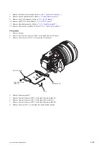
2-13-2. Control Switch Block (GZ92000)
Procedure
1.
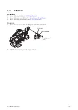
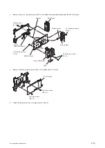
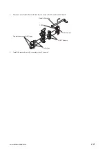
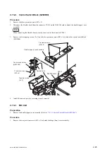
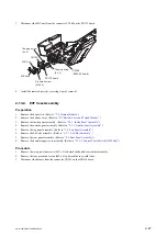
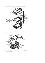
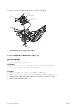
Remove the three precision screws (M2 x 5).
2.
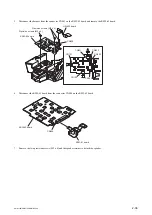
Disconnect the flexible board from the connector CN101 on the RM-238 board to detach the handle (upper) case
assembly.
Note
When connecting the flexible board, securely connect it to the connector CN101.
3.
Remove the two tapping screws (2 x 5) and the two precision screws (M2 x 4) to detach the control switch block
(GZ92000).
Precision screws
(M2 x 5)
Precision screws
(M2 x 4)
Tapping screws
(2 x 5)
CN101
RM-238 board
Flexible board
Hanlde (upper) case assembly
Control switch block
(GZ92000)
4.
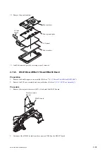
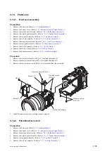
Install the removed parts by reversing steps of removal.
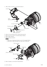
2-13-3. MIC Unit
Preparation
1.
Remove the handle (upper) case assembly. (Refer to
“2-13-2. Control Switch Block (GZ92000)”
.)
Procedure
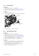
1.
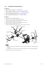
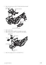
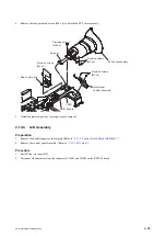
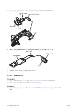
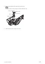
Remove the two precision screws (M2 x 5) to detach the hinge (front) cover assembly.
PMW-160/PMW-150/PMW-EX260
2-25
Summary of Contents for XDCAM PMW-160
Page 1: ...SOLID STATE MEMORY CAMCORDER PMW 160 PMW 150 PMW EX260 SERVICE MANUAL 1st Edition ...
Page 4: ......
Page 8: ......
Page 10: ......
Page 30: ......
Page 38: ...3 Install the removed parts by reversing steps of removal PMW 160 PMW 150 PMW EX260 2 8 ...
Page 92: ......
Page 128: ......
Page 130: ......
Page 131: ......

