background image

8

XDR-S3HD

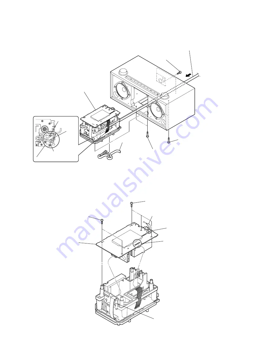
2-5. MAIN BOARD

2-4. CHASSIS ASSY

1

screw

     ((+) BV tapping (B3))

4

Pull the chassis assy 
out while pressing 
the power cord in the 
direction of the arrow.

2

two screws

     ((+) BV tapping (B3))

3

two screws

     ((+) BV tapping (B3))

5

Remove the three solders.

black with line

black

green

6

power cord

7

chassis assy

1

Remove the eight solders.

2

Remove the two solders.

black

4

three screws

     ((+) BV tapping (B3))

5

two screws

     ((+) BV tapping (B3))

6

MAIN board

3

 flexible flat cable (10 core)

    (CN4)

Summary of Contents for XDR-S3HD - HD / AM

Page 1: ... 05 FM AM DIGITAL RADIO HD Radio Broadcasting was approved by the Federal Communications Commission in October 2002 as the system for digital AM and FM broadcasting in the U S HD Radio technology features include Static free clear radio reception FM Multicasting the ability to broadcast multiple program streams over a single FM frequency A variety of data services including text based information ...

Page 2: ...oard TUNE Board 10 2 9 Assembly of the Power Cord 10 3 DIAGRAMS 3 1 Block Diagram 11 3 2 Printed Wiring Board Main Section 13 3 3 Schematic Diagram Main Section 14 3 4 Printed Wiring Boards Power Section 15 3 5 Schematic Diagram Power Section 16 3 6 Printed Wiring Board Micon Section 17 3 7 Schematic Diagram Micon Section 18 3 8 Printed Wiring Boards Key Section 19 3 9 Schematic Diagram Key Sectio...

Page 3: ...he remote commander no longer operates the unit replace all the batteries with new ones Notes Do not charge dry batteries When you are not going to use the remote commander for a long time remove the batteries to avoid any damage caused by leakage and corrosion Setting the clock 1 Plug in the unit The display will flash AM 12 00 2 Press MENU to show the menu display 3 Turn TUNE SELECT clockwise to...

Page 4: ...s off If you press DISPLAY while the display above appears the display changes to the following To return to the previous display press DISPLAY again A ALARM indicator B Alarm setting time C Alarm setting Source Frequency etc D Current time To deactivate the alarm function turn TUNE SELECT clockwise to select OFF in step 3 To stop the alarm Press POWER on the unit or remote commander Tips To enter...

Page 5: ...o connect the ground cord to the U terminal The supplied AM antenna cord has no polarity Tip Adjust the direction of the AM loop antenna for best AM broadcast sound To connect the FM antenna This unit comes supplied with an FM wire antenna and FM dipole antenna Connect an antenna that provides good reception to the FM antenna terminal Adjusting the FM wire antenna Be sure to fully extend the FM wi...

Page 6: ...Y Page 6 2 2 DC FAN M950 Page 7 SET 2 3 WIRES Page 7 2 6 POWER BOARD Page 9 2 9 ASSEMBLY OF THE POWER CORD Page 10 2 4 CHASSIS ASSY Page 8 2 5 MAIN BOARD Page 8 2 8 VOL BOARD TUNE BOARD Page 10 2 7 KEY BOARD Page 9 1 speaker net sub assy 2 five wood screws R 3 1 13 3 five wood screws R 3 1 13 8 panel front assy 4 5 flexible flat cable 18 core CN5 6 wire 3P CN305 7 wire 6P CN306 CNT board CN305 red...

Page 7: ... BV tapping B3 5 two screws BV tapping B3 6 two screws BV tapping B3 7 DC fan M950 8 cover fan 4 CN950 2P 2 two screws BV tapping B3 CN305 CN304 from TUNE board from VOL board from KEY board from speaker R ch from speaker L ch CN302 red red red red red ...

Page 8: ...n the direction of the arrow 2 two screws BV tapping B3 3 two screws BV tapping B3 5 Remove the three solders black with line black green 6 power cord 7 chassis assy 1 Remove the eight solders 2 Remove the two solders black 4 three screws BV tapping B3 5 two screws BV tapping B3 6 MAIN board 3 flexible flat cable 10 core CN4 ...

Page 9: ...3 7 chassis upper 9 chassis lower 8 POWER board 1 two screws BV tapping B2 6 3 FAN CNT board 2 Remove the three solders red 4 wire 6P CN303 red 7 1 button power 6 five screws 8 two screws 9 KEY board 0 panel key top 2 two buttons menu 3 two buttons enter 5 nine springs button 4 four buttons tone ...

Page 10: ...R CORD 2 8 VOL BOARD TUNE BOARD 3 9 1 knob jog 7 knob jog 5 VOL board qa TUNE board 6 escutcheon qs escutcheon 2 two screws 8 two screws 4 two screws 0 two screws When assembling the set route the power cord as shown below and install it ...

Page 11: ...907 D904 10V 5V AC IN 10V D231 STBY D130 AMP AMP D911 VDD1 8V 1 8V REG IC1 2 3 4 RESET IC403 1 2 J380 SP201 SPEAKER L CH i X401 32kHz 15 13 XIN XOUT X402 5 53MHz 17 SD_IBOC_OUT_I 9 18 BCK_IBOC_OUT 10 19 WS_IBOC_OUT 11 20 I2S_DATA 15 21 I2S_BCK 16 22 I2S_WS IF_I2S_Q1 IF_I2S_I1 IF_I2S_BCLK IF_I2S_WS AUDIO_I2S_DATA AUDIO_I2S_BCK AUDIO_I2S_WS 17 1 8V REG Q4 CVDD1 8V 8 5V MICON3 3V LED B 5V REG Q906 PO...

Page 12: ...no mark FM1 Voltages are taken with a VOM Input impedance 10 MΩ Voltage variations may be noted due to normal produc tion tolerances Waveforms are taken with a oscilloscope Voltage variations may be noted due to normal produc tion tolerances Circled numbers refer to waveform Signal path F FM f AM THIS NOTE IS COMMON FOR PRINTED WIRING BOARDS AND SCHEMATIC DIAGRAMS In addition to this the necessary...

Page 13: ...4 1 1 W701 8 3 4 5 3 1 B E C R59 Q6 R61 Q7 S1 S1 RESET CN2 CN1 FM AM BLK 1 1 27 TU1 DSP TUNER UNIT 2 WHT IC3 1 3 2 C7 JC3 C15 JC1 BLK JC2 R35 R49 C54 R53 1 2 17 CN5 18 10 9 2 1 CN4 C62 IC1 R18 IC4 R45 R46 R16 R15 R14 JW32 JW3 JW2 JW1 JW33 JW31 JW23 Q4 C16 JW24 JW8 JW7 JW26 JW25 JW10 JW6 JW4 JW5 JW9 JW11 JW27 JW28 JW18 JW17 JW19 JW12 JW13 JW14 JW15 JW16 JW30 Q5 C49 C55 JW22 JW29 JW21 C61 C58 TP1 TP...

Page 14: ... JW23 R15 JW24 R17 C60 R59 R57 R58 R16 R5 R6 R7 R8 R25 R26 R27 R28 R9 R10 R11 R12 FB1 FB2 FB3 FB4 FB5 FB6 TP1 TP2 TP3 TP4 JW32 R13 R55 R56 JW6 JW7 JW5 JW4 C27 C28 JW11 R24 C37 C36 C58 JW10 JW9 JW26 JW28 JW25 JW27 JW22 JW13 R35 C48 C49 R37 IC3 C57 C61 C59 JW15 JW16 JW18 JW17 R44 JW14 JW29 R61 JW12 S1 JW21 R47 R50 JW30 JW19 C62 R53 R18 CN4 CN5 CN1 CN2 IDM1 TU1 JC3 JC4 JC2 JC1 JC5 JW33 TH1 Q6 Q5 W701...

Page 15: ...R335 R331 Q952 B E C W702 Q951 C950 CN950 M950 DC FAN RED BLK 1 2 5 1 R952 R955 1 3 IC950 5 1 IC901 5 1 IC903 C180 J380 i T901 AC POWER UNIT C280 W703 RED 1 6 MARK BLU YEL BLK BRN R280 R180 R341 JW304 C332 C337 JW306 JW305 C150 C250 C155 C248 D130 D230 C130 C231 JW910 JW905 D915 D904 C234 C134 C230 JW230 C331 C333 C330 C148 C253 C153 C915 C905 Q903 C921 JW903 JW301 JW130 C131 C342 C255 JW131 IC302...

Page 16: ...W131 C154 C254 R148 R248 C340 R149 R150 R249 R250 C156 C256 R151 R251 R331 JW306 JW304 C342 C343 R341 D131 D231 JW305 C255 C155 SP101 SP201 CN302 C280 C180 R180 R280 CN303 Q907 Q908 Q913 Q912 C915 IC902 D916 D913 D914 C913 R914 JW903 JW905 C912 D906 R913 R912 C910 C909 Q904 Q905 JW902 R907 R940 JW910 IC901 R911 R910 R909 R908 C907 C906 D903 D901 D902 D904 Q901 C905 C904 C903 R906 R905 R901 R904 R9...

Page 17: ...TP417 TP441 TP412 TP401 TP414 TP415 TP413 TP411 TP422 IC403 R407 R420 R419 R418 R409 R408 C418 R425 R424 R423 R426 R427 TP426 TP424 TP405 TP404 TP402 TP403 TP425 TP428 R428 R434 E B C E B C E B C E B E C B C R433 Q405 Q404 C417 C416 C469 C468 R415 2 1 3 4 R520 X402 X401 R524 C415 R405 1 29 1 LCD401 LIQUID CRYSTAL DISPLAY PANEL 6 W705 R492 R493 C450 C451 C452 TP420 TP419 TP421 TP418 C454 C453 C455 ...

Page 18: ...1 C402 C403 R403 R405 R404 R401 C409 R406 R407 R408 R409 R418 R419 R420 JW408 JW417 IC403 C415 C414 R520 R524 R521 R415 R416 JW411 R519 JW407 JW412 R417 C450 C451 C452 C453 C454 C455 C456 C457 C458 C459 C460 R502 R504 JW419 JW403 JW404 R505 C461 R506 JW405 JW406 C462 R507 JW422 JW420 JW401 JW409 JW415 TP407 TP421 TP420 TP419 TP418 TP417 TP408 TP409 TP410 TP411 TP412 TP413 TP414 TP415 TP416 TP422 C...

Page 19: ... 3 6 1 1 6 6 1 CN305 CN304 S812 W707 1 3 3 2 1 W708 MARK BLU R831 JC831 JC835 JC830 RED MARK BLU YEL BLK BRN RED MARK BLU BLU MARK RED RED MARK BLU BLU MARK RED 1 3 BLU MARK RED JC832 JC834 JW834 CN306 R833 RED MARK BLU R832 R808 R807 R801 W706 R802 R804 R805 S801 S803 S804 S809 S806 POWER S801 SLEEP S802 S802 S808 S807 S805 BAND S803 RADIO LINE IN S804 PRESET S809 TONE S808 DISPLAY S807 MENU S805...

Page 20: ...332MR MAIN BOARD IC302 BA5417 POWER BOARD VREF CE EXT VSS VIN VOUT PROTECTION 1 5 3 2 4 VIN 1 CE 3 VSS 2 NC 4 VOUT 5 ON OFF CONTROL CURRENT LIMIT VOLTAGE REFERENCE VIN1 VIN2 SEL2 SEL1 A1 A2 B1 B2 C1 C2 FILTER GND CAP TNF1 TNF2 BNF2 BOUT2 BNF1 BOUT1 OUT1 OUT2 SI SC VCC BASS1 f0 80Hz BASS2 f0 80Hz 21 20 19 18 17 16 15 14 13 TREBLE2 f0 8kHz 22 TREBLE1 f0 8kHz 23 SURROUND 24 1 2 3 4 LOGIC VCC 2 VCC 2 ...

Page 21: ...E2 FAN CNT BOARD IC902 NJM2871BF33 TE2 POWER BOARD IC403 XC61CN2702NR MICON BOARD VREF VSS VOUT 1 4 NC VIN 2 3 5 VIN 4 VOUT 2 GND 3 NOISE BYPASS 1 CONTROL BANDGAP REFERENCE THERMAL PROTECTION 1 2 3 4 5 CURRENT LIMIT THERMAL PROTECTION OVERVOLTAGE PROTECTION BANDGAP REFERENCE VIN CONTROL VOUT VADJ GND ...

Page 22: ..._6 NC O Fixed at L level Not used 25 P7_5 NC O Fixed at L level Not used 26 P7_4 ATUNER_CLK O Analog tuner clock signal output Not used 27 P7_3 ATUNER_DI O Analog tuner data output Not used 28 P7_2 TA10OUT BEEP O Beep signal output 29 RXD2 DTUNER_SCL Communication pin for digital tuner 30 TXD2 DTUNER_SDA Communication pin for digital tuner 31 P6_7 SDA O Flash write pin Normally output port 32 P6_6...

Page 23: ... L level 76 P1_4 NC O Fixed at L level Not used 77 P1_3 KEY_LED O Key LED control signal output Not used 78 P1_2 NC O Fixed at L level Not used 79 P1_1 E2PROM_SCL O E2PROM clock signal output Not used 80 P1_0 E2PROM_SDA I O E2PROM data output Not used 81 P0_7 AN0_7 VOL_CLK O Clock signal output for sound IC communication 82 P0_6 AN0_6 VOL_DATA O Data output for sound IC communication 83 P0_5 AN0_5...

Page 24: ..._0 KEY OFF O A D key remote control receiver and rotary encoder power control signal output L normally H backup 98 VREF Reference voltage input for A D converter 3 3 V 99 AVCC Power supply pin for A D converter 3 3 V 100 P9_7 NC O Fixed at L level Not used ...

Page 25: ...ng these items XX and X mean standardized parts so they may have some difference from the original one Color Indication of Appearance Parts Example KNOB BALANCE WHITE RED Parts Color Cabinet s Color Accessory and parts list are given in the last of this parts list R R 1 X 2177 965 1 NET SUB ASSY SPEAKER 1 7 621 849 10 SCREW WOOD R 3 1X13 The components identified by mark 0 or dotted line with mark...

Page 26: ... X 2179 523 1 PANEL FRONT SUB ASSY 52 2 667 343 01 BUSHING 53 3 100 681 01 SHEET LCD DIFFUSION 54 3 100 680 01 PLATE LCD LIGHT GUIDE 55 3 100 679 01 REFLECTOR LCD 56 3 100 678 01 HOLDER LCD 57 X 2179 670 1 MICON BOARD COMPLETE 58 1 834 138 21 CABLE FLEXIBLE FLAT 18 CORE 59 3 252 827 01 SCREW B2 6 BV TAPPING LCD401 1 802 474 11 DISPLAY PANEL LIQUID CRYSTAL ...

Page 27: ...KNOB JOG 102 3 254 081 11 SCREW 103 3 100 674 01 ESCUTCHEON 104 A 1257 298 A VOL BOARD COMPLETE 105 3 100 672 01 BUTTON POWER 106 3 100 673 01 BUTTON MENU 107 3 106 282 01 BUTTON TONE 108 3 106 281 01 BUTTON ENTER 109 3 100 694 01 SPRING BUTTON 110 3 100 671 01 PANEL TOP KEY 111 A 1257 296 A KEY BOARD COMPLETE 112 A 1257 300 A TUNE BOARD COMPLETE SP101 1 826 688 11 SPEAKER 6 6cm R CH SP201 1 826 6...

Page 28: ...ied T901 M950 A A 151 X 2177 282 1 CABINET ASSY 152 3 218 790 01 CUSHION REAR COVER 153 3 100 682 01 COVER REAR 154 3 254 143 11 SCREW B3 BV TAPPING 155 3 100 687 01 SHEET FOOT ADHESIVE 156 3 100 683 01 FOOT 157 2 667 344 01 FOOT RUBBER 158 3 214 708 01 COVER FAN 159 3 254 145 11 SCREW B3 BV TAPPING 160 3 252 827 01 SCREW B2 6 BV TAPPING M950 1 787 396 11 FAN D C 50 SQUARE 0T901 1 480 224 11 POWER...

Page 29: ...3 BV TAPPING 204 A 1257 209 A MAIN BOARD COMPLETE 205 3 198 658 01 COVER DSP01 A 206 3 198 659 01 COVER DSP01 B 207 2 667 338 01 NUT ANTENNA 208 2 667 342 01 LUG 209 A 1257 294 A JACK BOARD COMPLETE 210 3 252 827 01 SCREW B2 6 BV TAPPING 211 A 1257 291 A POWER BOARD COMPLETE 212 3 100 676 01 CHASSIS LOWER 213 3 253 143 01 SCREW B2 6 P TAPPING 214 1 834 139 21 CABLE FLEXIBLE FLAT 10 CORE 215 3 100 ...

Page 30: ...KA T146 RESISTOR R950 1 216 841 11 METAL CHIP 47K 5 1 10W R951 1 216 841 11 METAL CHIP 47K 5 1 10W R952 1 216 821 11 METAL CHIP 1K 5 1 10W R953 1 216 829 11 METAL CHIP 4 7K 5 1 10W R954 1 216 805 11 METAL CHIP 47 5 1 10W R955 1 216 821 11 METAL CHIP 1K 5 1 10W A 1257 294 A JACK BOARD COMPLETE CAPACITOR C180 1 162 966 11 CERAMIC CHIP 0 0022uF 10 50V C280 1 162 966 11 CERAMIC CHIP 0 0022uF 10 50V JA...

Page 31: ...64 11 SHORT CHIP 0 JC2 1 216 864 11 SHORT CHIP 0 JC3 1 216 864 11 SHORT CHIP 0 JC4 1 216 864 11 SHORT CHIP 0 JC5 1 216 864 11 SHORT CHIP 0 MAIN TRANSISTOR Q4 8 729 034 00 TRANSISTOR 2SA1282ATP EF Q5 8 729 024 93 TRANSISTOR 2SB1565E Q6 6 551 700 01 TRANSISTOR ISA1602AM1TP 1F Q7 8 729 029 14 TRANSISTOR DTC144EUA T106 RESISTOR R1 1 216 864 11 SHORT CHIP 0 R2 1 216 864 11 SHORT CHIP 0 R3 1 216 864 11 ...

Page 32: ...P 0 1uF 10 16V C462 1 162 970 11 CERAMIC CHIP 0 01uF 10 25V C468 1 162 927 11 CERAMIC CHIP 100PF 5 50V C469 1 162 927 11 CERAMIC CHIP 100PF 5 50V C470 1 115 156 11 CERAMIC CHIP 1uF 10V CONNECTOR CN401 1 779 555 21 CONNECTOR FFC LIF NON ZIF 18P DIODE D401 6 501 880 01 LED SDPW31G0C0000 LCD BACK LIGHT D402 6 501 880 01 LED SDPW31G0C0000 LCD BACK LIGHT IC IC401 not supplied IC M3062LFGPFP IC403 6 702...

Page 33: ...R521 1 216 845 11 METAL CHIP 100K 5 1 10W R522 1 216 833 11 METAL CHIP 10K 5 1 10W R524 1 216 821 11 METAL CHIP 1K 5 1 10W R525 1 216 853 11 METAL CHIP 470K 5 1 10W R526 1 216 821 11 METAL CHIP 1K 5 1 10W Ref No Part No Description Remark VIBRATOR X401 1 813 202 11 VIBRATOR CRYSTAL 32kHz X402 1 813 988 21 VIBRATOR CERAMIC 5 53MHz A 1257 291 A POWER BOARD COMPLETE 3 253 143 01 SCREW B2 6 P TAPPING ...

Page 34: ...902 6 551 696 01 TRANSISTOR ISA1235AC1TP 1EF Q903 8 729 018 99 TRANSISTOR 2SD2394 F Q904 6 551 696 01 TRANSISTOR ISA1235AC1TP 1EF Q905 8 729 027 44 TRANSISTOR DTC114TKA T146 Q906 8 729 011 92 TRANSISTOR 2SC2001TP K1K2 Q907 6 551 696 01 TRANSISTOR ISA1235AC1TP 1EF Q908 8 729 027 44 TRANSISTOR DTC114TKA T146 Q909 8 729 620 07 TRANSISTOR 2SC3052EF T1 LEF Q910 6 551 696 01 TRANSISTOR ISA1235AC1TP 1EF ...

Page 35: ...1 METAL CHIP 100 5 1 10W R923 1 216 817 11 METAL CHIP 470 5 1 10W R924 1 216 825 11 METAL CHIP 2 2K 5 1 10W R925 1 216 817 11 METAL CHIP 470 5 1 10W R926 1 216 825 11 METAL CHIP 2 2K 5 1 10W R927 1 216 821 11 METAL CHIP 1K 5 1 10W R928 1 216 841 11 METAL CHIP 47K 5 1 10W R929 1 216 841 11 METAL CHIP 47K 5 1 10W R940 1 216 841 11 METAL CHIP 47K 5 1 10W A 1257 300 A TUNE BOARD COMPLETE RESISTOR R830...

Page 36: ...N HISTORY Clicking the version allows you to jump to the revised page Also clicking the version at the upper on the revised page allows you to jump to the next revised page Ver Date Description of Revision 1 0 2007 05 New ...

Reviews: