background image

Summary of Contents for XM-1600GSD Marketing Specifications, Connections

Page 1: ...cord The model and serial numbers are located on the bottom of the unit Record the serial number in the space provided below Refer to these numbers whenever OLI call LI OL I your Sony dealer regarding this product Model No XM IhOOCSD Serial No XM 1GOOGSD Sony Corporation Q2002 Printed in Korea ...

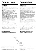
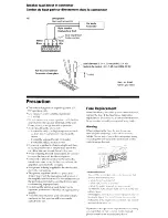
Page 2: ...til all the other leads have been connected Make the terminal connections as illustrated below Avant d effectuer les connexions d branchez la borne de masse de la batterie de voiture pour ter tout court circuit l Veillez a utiliser des haut parleurs de puissance ad quate Si 1s utilisez dcs haut parleurs de faible capacit6 ils risquent d tre endommag l Ne raccordez pas la borne 0 du syst me du haut...

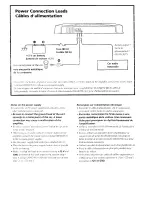
Page 3: ...Cirfrlfl c i iliP 12 v p1wr f p l hf olrll iificv i7li 1171 e iiirrrorif Ie iliblc d ahrer7tatiorz I2 V 7ir7iipcf77 vrl Oh i 11 17dS h7i C hWf1 COll ffi Cld 7jlk i7iWif rcc7lis hllrtes es alrtrce CO77I7 YiOf7S d Be sure toconnect the ground lead of the unit BRaccordez correctement le fii de masse 5 une secure y to a metal point of the car A loose partie mPtallique de la voiture Une connexion ...

Page 4: ...of switches arid controls refer to Location and Funcfion of Controls l You can connect either output terminal l The minimum resistance must be I 2 in total Pour plus de dt 7ilswr it5 r6j yes descommufnfclrrs ef commnrtdes reportrz oas ii Emplacemer tef foncfion descommandcs l Peu importe la borne desortic q e uous raccordez l La rt istanceminimale doit PtrcLignleh I L2AUfofal ...

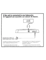
Page 5: ...If the unit is connected to two Subwoofers Si I appareil est raccordd h deux caissons de basses Car audio Autoradio ...

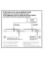
Page 6: ...aying back in stereo mode requires two units Si les appareils sont en mode de lecture St So La lecture en mode st o requieti deux appareils Right subwoofer min TOTAL 1 Q Caisson de grave gauche min TOTAL 1 Q Caisson de grave droit min TOTAL 1 52 ...

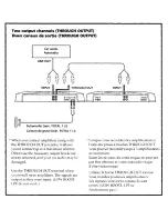
Page 7: ...d Use the THROUGH OUT terminal when you install more amplifiers The signals are output as they were input LOW BOOST LPF do not work Lorsque vous raccordez des amplificateurs B I aide des prises Bbroches THROUGH OUT vous pouvez raccorder jusqu b 3 amplificateurs au maximum Sinon Ies niveaux de sortie requis ne peuvent pas etre obtenus et votre autoradio risque d etre endommag6 Utilisez la borne THR...

Page 8: ...woofer Connexion d entke A haut niveau Comme amplificateur monaural pour un haut parleur d extrgmes graves Left speaker Haut parleur gauche Right speaker Haut parleur droit Input lead Not supplied Cdble d entr Non fournis Subwoofer Caisson de grave min TOTAL 1 Q ...

Page 9: ... before USC When installing the unit horizontally be sure not to cover the fins with the floor carpet etc l If this unit is PIaced too close to the car radio interference may occur In this case relocate th amplifier away from the car radio l If no power is being supplied to the master unit check the connections This power amplifier etnplovs a protection circuit to protect the transistors and spcak...

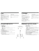
Page 10: ...ghts up in red when the temperature rises to an unsafe level TEST TONE button When this button is pressed if the test tone can be heard from the connected speakers operation is normal Cut off frequency adjustment control Sets the cut off frequency 50 300 Hz for the low pass filters LOW BOOST level control Turn this control to boost the frequencies around 40 Hz to a maximum of 1U dB LEVEL adjustmen...

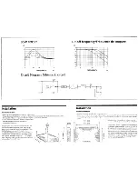
Page 11: ...d mount the unit onto the board with the supplied mounting screws The supplied mounting screws are v in 15 mm long Therefore make sure that the mounting board is thicker than 1 in 15 mm Avant I installation l Installez l appareil dans le coffre OLI sous un siPge l Choisissez un endroit de montage judicieux pour que l appareil ne g e pas les mouvements naturel conducteur et pour qu il ne soit pas e...

Page 12: ...l N inst Y em Tout d I instal t de la p trous s millim Q avec 1 2 fournil z assure 01 V v p ...

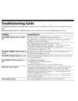
Page 13: ...icator light UP Turn off the power switch The speaker outputs are short circuited in red Rectify the cause of the short circuit The OFFSET indicator lights up in red Turn off the power switch Make sure the speaker lead and ground lead are securely connected The THERMAL indicator lights up in The unit heats up abnormally red l Use speakers with suitable impedance 1 to 8 Q stereo l Make sure to plac...

Page 14: ...200 w at 2 n Rated outputs supply voltage at 14 4 V 300 W 20 HT 300 Hz 0 2 I THD at 4 Q 600 W 20 Hz 300 Hz 0 6 i THD at 2 Q 1000 W 20 Hz 300 Hz 1 2 4 THD at 1 12 Frequency response 5 Hz 3110Hz YdB Input level adjustment range 0 2 6 0 V RCA pin jacks 0 4 12 0V High level input Lowpass filter 50 300 Hz 12 dB oct Low boost 0 10dB 40 Hz Power supply voltage 10 5 16V Current drain at rated output 40 A ...

Page 15: ... such as fuses or batteries This warranty is valid only in the United States Proof of purchase in the form of a bill of sale or receipted invoice Warranty period must be presented to obtain warranty service which is evidence that the unit is within the This warranty is invalid if the factory applied serial number has been altered or removed from the Product REPAIR OR REPLACEMENT AS PROVIDED UNDER ...

Reviews: