– 4 –
SECTION 2
DISASSEMBLY
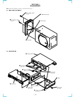
Note:
Follow the disassembly procedure in the numerical order given.
2-1. AMPLIFIER ASSEMBLY
2-2. MAIN BOARD
1
Two tapping screws
(4x30)
2
Two tapping screws
(4x30)
3
Wire (White)
5
Amplifier assembly
4
Wire (Red)
1
Fuse (F901)
(Brade type)
5
Heat sink (MAIN)
8
Main board
9
Pull out a Wire.
0
Panel
2
Two screws
(BTP 3x8)
3
Two screws
(BTP 3x8)
4
Four screws
(BTP 3x8)
6
Three screws
(BTP 3x10)
7
Five screws
(BTP 3x10)


