11
SECTION 5
ELECTRICAL ADJUSTMENTS
MAIN SECTION
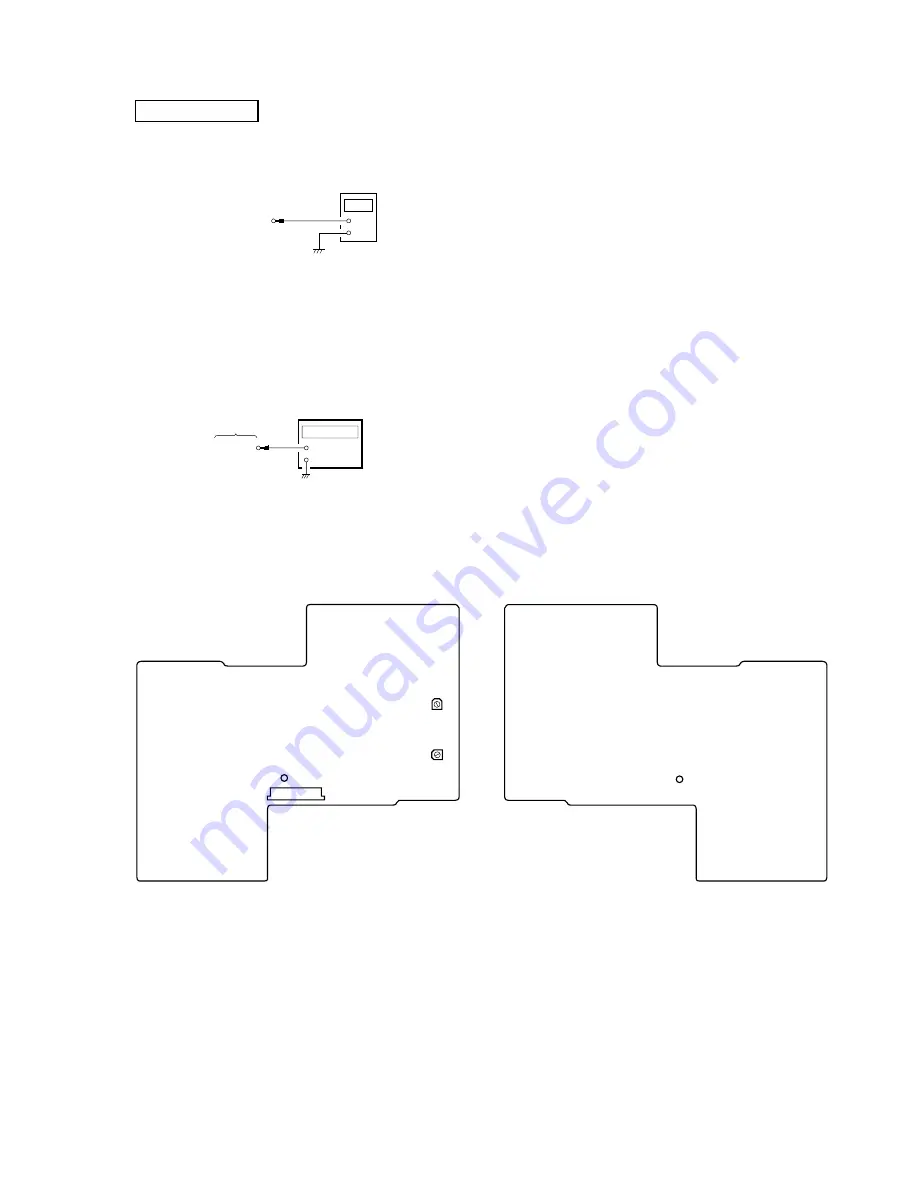
5.35 V Adjustment
Connection:
Adjustment Procedure:
1. Connect a digital voltmeter to the TP1 (5.35 V) on the A board.
2. Adjust RV501 on the A board so that digital voltmeter reading
is 5.35 V.
Inverter Standard Frequency Adjustment
Connection:
Adjustment Procedure:
1. Connect a frequency counter to the CL299 on the A board.
2. Adjust RV502 on the A board so that frequency counter read-
ing is 115 ± 2 kHz.
Adjustment Location:
digital voltmeter
A board
TP1 (5.35 V)
+
–
RV501
5.35 V
Adjustment
RV502
INVERTER
STANDARD
FREQUENCY
Adjustment
TP1 (5.35 V)
CN401
– A BOARD (Side A) –
A board
CL299
+
–
frequency counter
CL299
– A BOARD (Side B) –


