10
XVM-H6
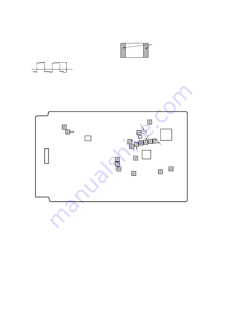
3-17. VCOM BIAS ADJUSTMENT
1. Display gray scale on the monitor screen.
2. Connect oscilloscope to the Q703 No. 2.
3. Adjust the semi-fixed resistor VCDC until the levels A and B of
the output waveform stand at their respective specified values.
Specified value: A: 4.40 ± 0.04 V
B: 1.43 ± 0.04 V
3-18. BLANK LEVEL ADJUSTMENT
1. Display gray scale on the monitor screen. Set the screen to the
Normal mode.
Adjustment Location:
VFRQ
VR+5
– DISPLAY BOARD – (CONDUCTOR SIDE)
L305
C302
VSUR
VCOA
VCOL
VTIN
VCOM
VSUB
VCNT
VPIC
VBRI
VRGB
VGA1
VFREQ
VCDC
VGA2
VHIG
Q703
Q701
(COMPONENT SIDE)
U2
U600
VLOW
If not black on the right and left ends,
adjust VHIG and VLOW so that black
vertical bands appear on the right and
left ends of the screen.
A
GND level
B


