2
XVM-R75
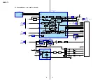
When measuring, the ground should be connected to the ground (pin 15 of connector B1) in the display board unless otherwise specified.
1-1. EQUIPMENT USED
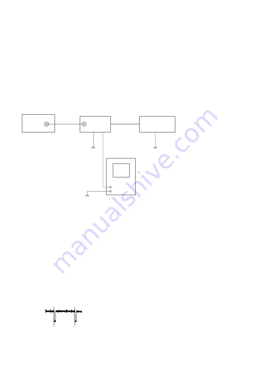
The following measuring equipment are used for these electrical adjustments:
• Oscilloscope
• NTSC pattern generator
• Stabilized power supply
• Digital voltmeter
• Frequency counter
• Connection box (XA-117)
1-2. CONNECTION OF EQUIPMENT
1-3. 5V ADJUSTMENT
1. Display gray scale on the monitor screen.
2. Connect digital voltmeter to the C10 position of L19.
3. Adjust VR1 so that the reading on the voltmeter stands at the specified value.
Specified value: 5.00 ± 0.05 V
1-4. FREQUENCY ADJUSTMENT
This frequency adjustment on the DC-DC converter is only performed if there is switching noise mixed on the screen.
Adjust RV20 to a position in which no noise appears on the screen.
1-5. PLL FREE RUN FREQUENCY ADJUSTMENT
1. Make the input signal no signal.
2. Connect frequency counter to pin
th
of IC U705.
3. Adjust the semi-fixed resistor VFRER until the frequency is at 15895 ± 20 Hz.
VIDEO IN
VIDEO
G
N
D
B+
pattern generator
connection box
XA-117
monitor
XVM-R75
stabilized
power supply
14.4V
Summary of Contents for XVM-R75
Page 47: ...15 XVM R75 MEMO ...


