7
XVM-R75
SECTION 2
DISASSEMBLY
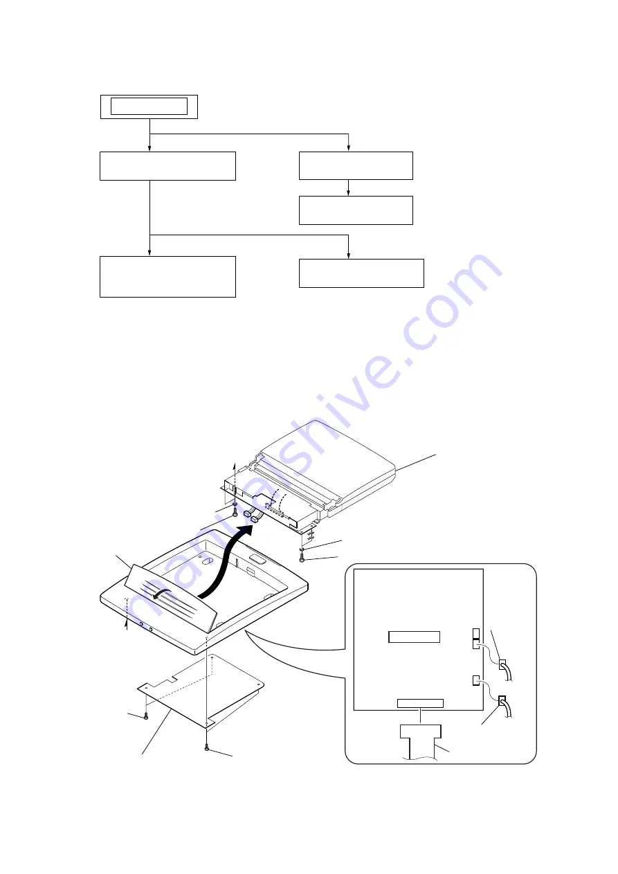
Note : This set can be disassemble according to the following sequence.
Note : Follow the disassembly procedure in the numerical order given.
2-1.
LCD BLOCK ASSY
(Page 7)
SET
2-4.
MOTOR (M1),
MICRO SW BOARD
(Page 9)
2-2.
CONNECTORS
(Page 8)
2-3.
MAIN BOARD
(Page 8)
2-5.
DISPLAY BOARD
(Page 9)
2-1. LCD BLOCK ASSY
A
A
1
P 2x5
7
PS 3x6
9
PS 3x6
8
spring washers
qd
LCD block assy
MAIN board
flap
0
spring washers
qa
qs
4
connector (B14)
6
connector
(B5)
5
connector
(B4)
2
P 2x5
3
shield plate
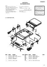
Summary of Contents for XVM-R75
Page 47: ...15 XVM R75 MEMO ...


