<SNC-EP520/521/550/580
、
ER520/521/550/580
、
ZP/ZR 550>
3
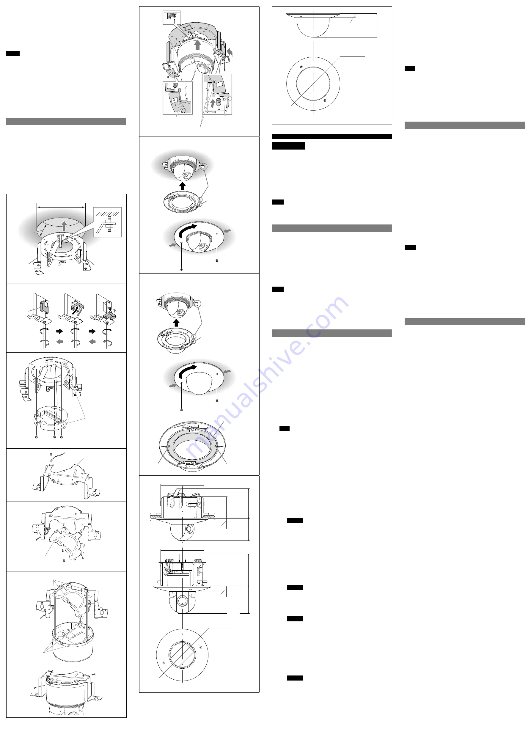
ネジをはずし、ブラケットを時計回りに回転させながら天井埋め
込み金具から取りはずす。
4
天井埋め込み金具からワイヤーロープを取りはずす。
6
金具の左右の固定板が縦になるまで、左右のネジを反時計回りにゆるめ
る。
7
アンカーボルトをゆるめて天井から金具をはずす。
ご注意
固定板が閉じた状態から、さらに取りはずし方向へネジを回さないでくだ
さい。固定板が上部に強く突き当たると破損の可能性があります。
ネジをゆるめるときは金具や天井ユニットを押さえてください。金具や
天井ユニットが落ちる危険があります。
YT-LD124C/LD124S
(ドームカバー)
1
ドームカバーを天井に押さえつけながらネジをはずす。
2
反時計回りに回して取りはずす。カバーは垂直方向にはずしてくださ
い。
カバーが回らない場合は、ドームカバーの両脇を押しながら(
a
)回し
てください。
仕様
YT-ICB124
(天井埋め込みキット)
質量
約
930g
(カバーを含む)
約
1,500g
(カバー、ブラケット、スペーサを含
む)
外形寸法
図
をご覧ください。
付属品
テンプレート
(1)
、
M4
×
10
ネジ
(6)
、取付説明
書
(1
式
)
、ワイヤーロープ
(1)
、ブラケット
(1)
、ス
ペーサ
(1)
別売アクセサリー
ドームカバー
(
クリア
)
YT-LD124C
ドームカバー
(
スモーク
)
YT-LD124S
YT-LD124C/LD124S
(ドームカバー)
質量
約
400 g
外形寸法
図
をご覧ください。
付属品
取付説明書
(1
式
)
φ
233 to 237 (9
1
/
4
to 9
3
/
8
) hole
Ceiling
Fixing
plate
10 to 35
(
13
/
32
to 1
7
/
16
)
Fixing
plate
Unit: mm (inches)
Fixing
plate
Installation
Removal
Align the marks
M4 supplied screws
Bracket
Spacer
M4 supplied screws
Spacer/bracket tab
Groove in the
camera bottom
Align the marks
Align at this position
Align at this position
Align the marks
Protrusion (round type)
a
a
Align the marks
Protrusion (round type)
a
a
Inner cover
Screw
Screw
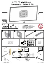
225.7 (9)
ø270 (10
3
/
4
)
112.1 (4
1
/
2
)
152.1 (6)
23.8 (
15
/
16
)
115.5 (4
5
/
8
)
225.7 (9)
152.1 (6)
23.8 (
15
/
16
)
130.4 (5
1
/
4
)
Unit: mm (inches)
ø270 (10
3
/
4
)
21.2 (
27
/
32
)
122.4 (4
7
/
8
)
Unit: mm (inches)
English
WARNING
This installation should be made by a qualified service person and
should conform to all local codes.
Ensure that the installation location is strong enough to support a
load of over 60 kg before installing the camera securely; otherwise
the camera may fall and cause serious injury. If they are not strong
enough, the camera may fall and cause serious injury.
To prevent the camera from falling, be sure to attach the supplied
wire rope.
If you install the camera at a height, check periodically, at least once
a year, to ensure that the connection has not loosened. If conditions
warrant, perform this periodic check more frequently.
Notes
Use the supplied screws for the installation. Using screws other than those
supplied may seriously damage the inside of the camera.
Avoid using or storing the unit in a place subject to strong vibration or
shock.
Overview
YT-ICB124 is a kit for use with the following series of models: SNC-RH124/
RS46N/RS46P/RS44N/RS44P, SNC-EP520/521/550/580, SNC-ER520/521/550/
580 and SNC-ZP/ZR550.
It is used when the body of the camera is embedded in the ceiling, or with
gypsum boards and such where the material used in the ceiling is too fragile
to hold ordinary screws.
Install the camera on the ceiling with the thickness from 10 mm to 35 mm
(
13
/
32
~ 1
7
/
16
inches) inclusive.
YT-LD124C is a clear dome cover and YT-LD124S is a smoked dome cover for
the camera.
When using this dome cover, the in-ceiling kit (YT-ICB124/ICB630) is
required.
Notes
YT-ICB124 (In-ceiling kit) is for indoor use. It cannot be used for installation
outdoors.
Using YT-LD124C/LD124S (dome cover) may cause deterioration of the
camera’s optical performance due to image distortion and luminous spots,
etc. If you use a grey-smoke dome cover, the brightness of the screen
becomes darker by about 1 aperture.
Do not use YT-LD124C/LD124S (dome cover) attached in a place where the
temperature becomes more than 40°C (104°F).
Installing
YT-ICB124 (In-ceiling kit)
1
Make a ø235 ± 2 mm (9
3
/
8
±
3
/
32
inches) hole in the ceiling.
Use the supplied template.
Use the four slotted holes on the template to decide the center position
of the camera.
2
Fix the in-ceiling bracket to the ceiling with an anchor bolt (anchor
bolts are not supplied).
Make sure that the fixing plates on both sides of the bracket are in the
lengthwise position (factory default), and install the bracket in the hole
in the ceiling. (
)
The
¯
hole in the bracket shows the front side of the camera.
Adjust the direction when attaching the in-ceiling kit as necessary.
3
Tighten the left and right screws of the bracket. The bracket should grip
the ceiling.
As you tighten the screws clockwise, the upright fixing plates swing
outward and open. When you tighten the screws further, the fixing
plates swing lower and grip the ceiling. (
)
Ensure that the fixing plates are gripping the ceiling firmly.
Note
Torque the screws to 1.0 N•m (10 kgf•cm) or less to tighten them.
Tightening the screws too much may cause damage to the in-ceiling
bracket.
<SNC-RH124, RS46N/RS46P, RS44N/RS44P>
4
Connect the cable and the ceiling unit wire rope to the ceiling unit
of the camera.
¿
For details, see the Installation Manual of the camera.
5
When you insert the ceiling unit into the bracket completely, the
arm temporarily supports the ceiling unit.
Position the
¯
hole in the bracket (indicating the front) and the
front side mark on the ceiling unit.
Match the protrusions of the bracket with the holes in the
ceiling unit. Make sure that the protrusions fit the holes.
Align the holes in the ceiling unit with the screw holes in the
bracket.
6
Using the supplied
M4
Ï
10 screws, attach the ceiling unit of the
camera to the in-ceiling bracket. (
)
Warning
Always fix with the supplied screws. Using screws other than
those supplied may cause the camera to fall, which may cause
serious injury.
Using the device with temporary fixture may result in the camera
falling, which may cause serious injury.
7
Insert the camera into the ceiling unit until you hear a click.
Push the Lock button to confirm the camera is locked.
¿
For details, see the Installation Manual of the camera.
<SNC-EP520/521/550/580, ER520/521/550/580, ZP/ZR 550>
4
Connect the wire rope to the supplied bracket using the supplied
M4×10 screws. (
)
When using the dome cover (sold separately), go to step 6.
Warning
Always fix with the supplied screws. Using screws other than
those supplied may cause the camera to fall, which may cause
serious injury.
5
Install the spacer on the bracket using the supplied
M4x10
screws. (
)
Warning
Always fix with the supplied screws. Using screws other than
those supplied may cause the camera to fall, which may cause
serious injury.
6
Align the spacer/bracket tabs with the grooves in the camera
bottom, then secure the camera with the supplied screws. (
)
(
)
¿
For details, see the Installation Manual of the camera.
7
Attach the wire rope to the in-ceiling bracket. Insert the bracket
into the in-ceiling bracket by aligning their positions
, turn the
bracket counterclockwise until it stops
, and then fix it in place
with the supplied
M4×10 screws. (
)
Warning
Always fix with the supplied screws. Using screws other than
those supplied may cause the camera to fall, which may cause
serious injury.
Using the device with temporary fixture may result in the camera
falling, which may cause serious injury.
8
Attach the cover (supplied). (
)
Place the cover over the in-ceiling bracket and turn the cover
clockwise to fix it.
When installing the cover, match the right protrusion (square type)
on the cover with the notch in the bracket. Then turn the cover
clockwise until the left protrusion (round type) meets the notch.
Secure the cover with screws.
See the following “YT-LD124C/LD124S (dome cover)” to install the
purchased dome cover.
YT-LD124C/LD124S (dome cover)
Remove the inner cover for a wider area view.
Note
The lens zoom and angle may result in a blurred or inclined image of the
area covered by inner cover.
1
Place the dome cover over the in-ceiling bracket and turn the cover
clockwise to fix it.
When installing the cover, position the right protrusion (square type) of
the dome over the notch in the bracket. Then turn the cover clockwise
until the left protrusion (round type) meets the notch.
2
Secure the dome cover with screws.
3
Remove the protective sheet on the dome cover.
Removing
YT-ICB124 (In-ceiling kit)
1
Hold the cover and then, remove the screws on the cover.
2
Remove the cover by turning it counter-clockwise and the cover down
vertically.
If it can not be turned, turn the cover while pushing both side (
a).
<SNC-RH124, RS46N/RS46P, RS44N/RS44P>
3
Remove the camera from the ceiling unit.
For details, see the Installation Manual of the camera.
4
Loosen the screws and remove the ceiling unit from the bracket.
5
Remove the cable connecting to the ceiling unit and the wire rope.
For details, see the Installation Manual of the camera.
<SNC-EP520/521/550/580, ER520/521/550/580, ZP/ZR550>
3
Remove the screws, then rotate the bracket clockwise to remove it
from the in-ceiling bracket.
4
Remove the wire rope from the in-ceiling bracket.
6
Loosen the left and right screws of the bracket by turning them
counter-clockwise until the fixing plates are in the lengthwise position.
7
Loosen the anchor bolt and remove the bracket from the ceiling.
Notes
Do not attempt to further loosen the left and right screws of the In-Ceiling
Bracket when the fixing plates are in a closed position. Damage may be
incurred if the fixing plates forcefully press against the upper part of the
In-Ceiling Bracket.
Hold the bracket and ceiling unit while loosening screws. Otherwise the
bracket and ceiling unit may fall.
YT-LD124C/LD124S (dome cover)
1
Hold the dome cover on the ceiling and remove the screws.
2
Remove the cover by turning it counter-clockwise and the cover down
vertically.
If it can not be turned, turn the dome cover while pushing both side
(
a).
Specifications
YT-ICB124 (In-ceiling kit)
Mass
Approx. 930g (2 lb 0.8 oz) (including cover)
Approx. 1,500g (3 lb 4.9 oz) (including cover,
bracket and spacer)
Dimensions
See
.
Supplied accessories
Template (1),
M4
Ï
10 screws (6), Installation
Instructions (1 set), Wire rope (1), Bracket (1),
Spacer (1)
Optional accessories
Dome cover (clear) YT-LD124C
Dome cover (smoked) YT-LD124S
YT-LD124C/LD124S (dome cover)
Mass
Approx. 400 g (14 oz)
Dimensions
See
.
Supplied accessories
Installation Instructions (1 set)


