11
Caution
Danger
Caution
Caution
C.2 Electrical connection
Before working on the unit, switch off the power supply and secure
it against being switched on again! Check for the absence of power!
Electrical connections may only be made by a specialist and in
compliance with the applicable regulations.
Do not use the controller if the housing shows visible damage.
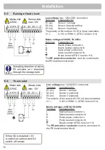
Low-voltage cables such as temperature sensor cables must be routed
separately from mains voltage cables. Feed temperature sensor cables
only into the left-hand side of the unit, and mains voltage cables only
into the right-hand side.
The customer must provide an all-pole disconnecting device, e.g. a
heating emergency switch.
The cables being connected to the unit must not be stripped by more
than 55mm, and the cable jacket must reach into the housing just to the
other side of the strain relief.
We recommend the use of fl exible cables to ease the installation in the
clamp room.
Caution
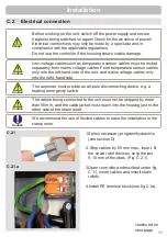
1.Select necessary program/hydraulics
(see section D)
2. Strip cables by 55 mm max., insert, fi t
the strain relief devices, strip the last
9-10 mm of the wires. (Fig. C.2.1)
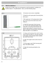
3.Open controller as described under fi g.
C.1.1, insert cables and install strain
reliefs
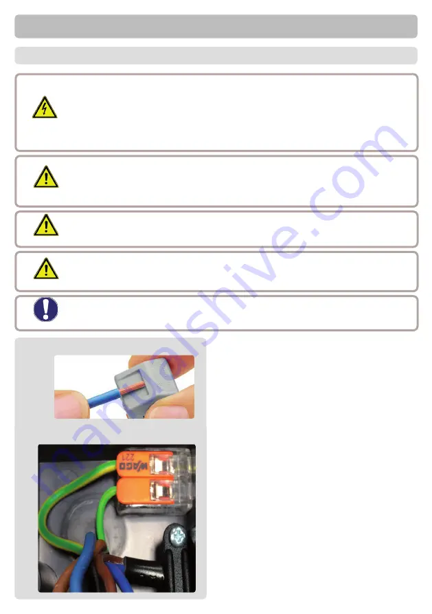
4.Install PE terminal block (see fi g. 2.1.a).
Installation
continued on
next page
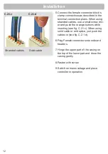
C.2.1
C.2.1.a


