background image

4

A.4   Changes to the unit

A.5   Warranty and liability

The controller has been manufactured and tested with regard to high quality
and safety requirements. The unit is subject to the statutory guarantee period
of two years from the date of sale.
The warranty and liability shall not include, however, any injury to persons or
material damage that is attributable to one or more of the following causes:

- Failure to observe these installation and operating instructions
- Improper installation, commissioning, maintenance and operation
- Improperly executed repairs
- Unauthorised structural changes to the unit
- Installation of additional components that have not been tested together with 

the unit

- Any damage resulting from continued use of the unit despite an
 obvious 

defect

- Failure to use original spare parts and accessories
- Use of the device for other than its intended purpose
- Operation above or below the limit values listed in the
 specifi cations
- Force majeure


- Changes, additions to or conversion of the unit are not permitted


  without the written permission from the manufacturer


- It is likewise forbidden to install additional components that have not


  been tested together with the unit


- If it becomes clear that safe operation of the unit is no longer possible,


  for example because of damage to the housing, then turn the controller


off 

immediately


- Any parts of the unit or accessories that are not in perfect condition


  must be exchanged immediately


- Use only original spare parts and accessories from the manufacturer.


- Markings made on the unit at the factory must not be altered,


  removed or made illegible


- Only the settings actually described in these instructions may be made


  on the controller

Changes to the unit can compromise the safety and function of the
unit or the entire system.nit or the entire system.

Safety instructions

Danger

Summary of Contents for TDC 1

Page 1: ...Read carefully before installation commissioning and operation Temperature Difference Controller TDC 1 Installation and operating instructions TDC 1 Temperature Difference Controller...

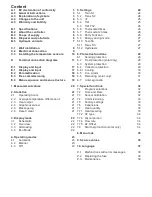
Page 2: ...ing 22 3 4 Eco Mode 22 4 Operating modes 23 4 1 Automatic 23 4 2 Manual 23 4 3 Off 23 5 Settings 24 5 1 Tmin S1 24 5 2 Tmax S2 24 5 3 T 25 5 4 Tref 25 5 5 Tref Th2 26 5 6 Thermostat times 26 5 7 Therm...

Page 3: ...id accident prevention regulations the regulations of the local power utility the applicable standards and the installation and operating instruction of the additional system components must also be o...

Page 4: ...Use of the device for other than its intended purpose Operation above or below the limit values listed in the specifications Force majeure Changes additions to or conversion of the unit are not permit...

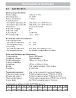
Page 5: ...oisture condensation permitted Other specifications and dimensions Housing design 2 part ABS plastic Installation methods Wall installation Overall dimensions 163mm x 110mm x 52mm Aperture installatio...

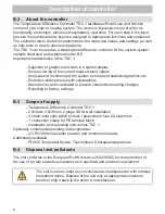
Page 6: ...manufacturer B 2 About the controller The Temperature Difference Controller TDC 1 facilitates efficient use and function control of your solar or heating system The device is impressive most of all f...

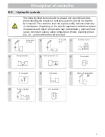
Page 7: ...under any circumstances Depending on the specific application additional system components and safety components may be mandatory such as check valves non return valves safety temperature limiters sca...

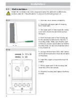
Page 8: ...re not to touch the electronics when doing so 4 Hold the lower part of the housing up to the selected position and mark the 3 mounting holes Make sure that the wall surface is as even as possible so t...

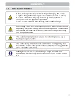
Page 9: ...ables must be routed separately from mains voltage cables Feed temperature sensor cables only into the left hand side of the unit and mains voltage cables only into the right hand side Caution The cus...

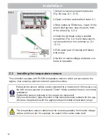
Page 10: ...he temperature sensors The temperature sensor cables must be routed separately from mains voltage cables and must not for example be routed in the same cable duct The controller operates with Pt1000 t...

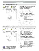
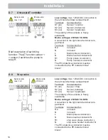
Page 11: ...onductor N The PE protective conductor must be connected to the PE metal terminal block Low voltage max 12VAC DC connection in the left hand terminal compartment Terminal Connection for S1 2x Sensor 1...

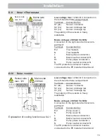
Page 12: ...to the PE metal terminal block Low voltage max 12VAC DC connection in the left hand terminal compartment Terminal Connection for S1 2x Sensor 1 storage S2 2x Sensor 2 backward flow S3 2x Sensor 3 opti...

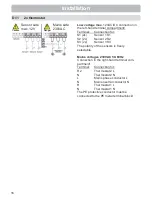
Page 13: ...and S2 switch off sensor Caution Installation Low voltage max 12VAC DC connection in the left hand terminal compartment Terminal Connection for S1 2x Sensor 1 storage S2 2x Sensor 2 storage S3 2x Sens...

Page 14: ...onnection in the left hand terminal compartment Terminal Connection for S1 2x Sensor 1 control S2 2x Sensor 2 reference S3 2x Sensor 3 optional The polarity of the sensors is freely selectable Mains v...

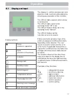
Page 15: ...ck Installation Sensor side max 12V Caution Mains side 230VAC Low voltage max 12VAC DC connection in the left hand terminal compartment Terminal Connection for S1 2x Sensor 1 collektor S2 2x Sensor 2...

Page 16: ...ctable Mains voltages 230VAC 50 60Hz Connection in the right hand terminal com partment Terminal Connection for R2 Thermostat 2 L N Thermostat 2 N L Mains phase conductor L N Mains neutral conductor N...

Page 17: ...ode Manual The LED 2 flashes quickly red when an error is present Entries are made using four keys 3 4 which are assigned to different functions depending on the situation The esc key 3 is used to can...

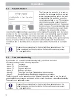
Page 18: ...k step by step to the selection mode thus cancelling the commissioning help Finally under operating mode menu 4 2 Manual should be used to test the switch outputs with the consumers connected and to c...

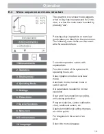
Page 19: ...rol of the system with operating hours etc Select graphics mode or overview mode Automatic mode manual mode or switch unit off Set parameters needed for normal operation Solar and frost protection rec...

Page 20: ...ay instead of the measurement value then there may be a defective or incorrect temperature sensor If the cables are too long or the sensors are not placed optimally the result may be small deviations...

Page 21: ...controller various time ranges day year are available 2 2 Average temperature difference T Display of the average temperature difference between the reference sensors of the solar system with the con...

Page 22: ...phics mode the selected hydraulic systems are depicted with the measured temperatures and operating states of the connected consumers 3 2 Overview In overview mode the measured temperatures and operat...

Page 23: ...us the connected consumer are switched on and off by pressing a key with no regard to the current temperatures and the parameters which have been set The measured temperatures are also shown to provid...

Page 24: ...his value again and the other conditions are also met then the controller switches the pump and or valve on again Setting range from 0 C to 99 C can be switched off in thermostat systems Default setti...

Page 25: ...Off 0 C 99 C Default 60 C Settings Switching condition Temperature difference for relay R If the temperature difference T between the reference sensors is exceeded and the other conditions are also me...

Page 26: ...ture is reached Settings 5 5 Tref Th2 Reference temperature at sensor1 for thermostat 2 Heating 1 value smaller than the 2 value If the temperature drops below Tref On 1 value at sensor 2 and the ther...

Page 27: ...ecoS3 hysteresis is reached Settings range 2 C to 20 C Default 10 C Hysteresis of the cooling function via S3 Sets the hysteresis for the cooling function of the storage If the temperature at S3 drops...

Page 28: ...y A two stage frost protection function can be activated In stage 1 the controller switch es the pump on for 1 minute every hour if the collector temperature drops below the set value Frost stage 1 If...

Page 29: ...ly priority protection System protection prevents overheating of system components by automatic shutdown of the solar pump If AS Ton is exceeded at the collector the pump is switched off The pump is a...

Page 30: ...witched off Once the storage tank at S3 exceeds TsetS3 cooling at R2 is switched on till TsetS3 hysteresis is reached 6 4 1 Cooling In hydraulic systems with solar when the recooling function is activ...

Page 31: ...h Default daily 3 5h During the anti Legionella function the storage tank is heated up over the set value Tmax S2 which can lead to scalding and damage to the system This anti Legionella function does...

Page 32: ...unpredictable errors For analysis of the system data it is essential for the time to be set ac curately on the controller Please note that the clock does not continue to run if the mains voltage is i...

Page 33: ...it if desired Pressing the esc more than once takes you back to the selection mode thus cancelling the commissioning help Caution May only be started by a specialist during commissioning Observe the e...

Page 34: ...ction should only be activated by a specialist if problems arise with acquisition of measurement values In particular follow the instructions from the collector manufacturer Special functions Caution...

Page 35: ...listed below remain completely accessible despite the menu block being activated and can be used to make adjustments if necessary 1 Measurement values 2 Analysis 3 Display mode 7 2 Time date 8 Menu lo...

Page 36: ...es can be used for remote diagnosis by a specialist or the manufacturer in the event of an error etc Caution Enter the values at the time when the error occurs e g in the table The menu can be closed...

Page 37: ...e language for the menu guidance This is queried automatically during initial commissioning The choice of languages may differ however depending on the device design Language selection is not availabl...

Page 38: ...ialist in the event of an error Malfunctions Error messages Notes for the specialist Sensor x defective Either the sensor the sensor input at the controller or the connecting cable is was defective Re...

Page 39: ...switch off the power supply and secure it against being switched on again Check for the absence of power Only use the supplied spare fuse or a fuse of the same design with the following specifications...

Page 40: ...est possible care the possibility of incorrect or incomplete information cannot be excluded Subject as a basic principle to errors and technical changes TDC1 ST_Englisch121994 Manufacturer SOREL GmbH...

Reviews: