background image

8

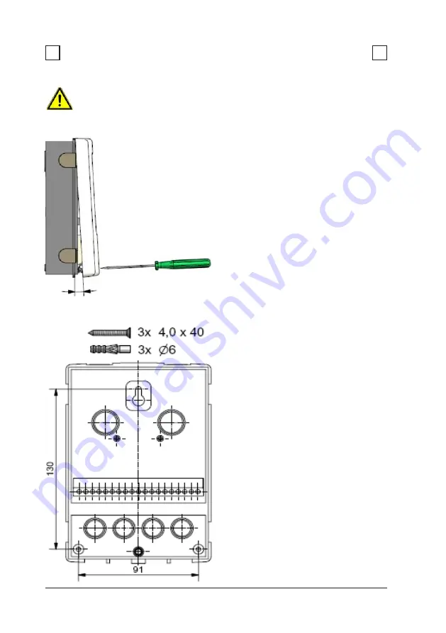
3.1 Wall installation

Installation

3

3

Caution

Install the controller only in dry areas and under the ambient
conditions described under 2.1 “Specifications

. Carry out the

following steps 1-8.

A

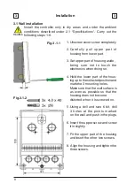
       Fig.3.1.1

Fig.3.1.2

1.Unscrew cover screw completely

2.Carefully pull upper part of

housing from lower part.

3.Set upper part of housing aside,

being sure not to touch the
electronics when doing so.

4.Hold the lower part of the hous-

ing up to the selected position and
mark the 3 mounting holes.
Make sure that the wall surface is
as even as possible so that the
housing does not become
distorted when it is screwed on.

5.Using a drill and size 6 bit, drill

3 holes at the points marked
on the wall and push in the plugs.

6.Insert the upper screw and screw

it in slightly.

7.Fit the upper part of the housing

and insert the other two screws.

8. Align the housing and tighten the

three screws.

Summary of Contents for TDC 2

Page 1: ...1 Temperature Difference Controller TDC 2 Installation and operating instructions Read carefully before installation commissioning and operation...

Page 2: ...Sensor calibration 12 4 Commissioning 12 5 Factory settings 12 6 Expansions 12 7 Heat quantity 12 8 Start help 12 9 Speed control 12 25 25 25 26 26 26 26 27 28 Useful notes 17 34 Chapter Page Chapter...

Page 3: ...ns the regulations of the local power utility the applicable DIN EN standards and the installation and operating instruction of the additional system components must also be observed The controller do...

Page 4: ...ginal spare parts and accessories Use of the device for other than its intended purpose Operation above or below the limit values listed in the specifications Force majeure Changes additions to or con...

Page 5: ...ed Other specifications and dimensions Housing design 2 part ABS plastic Installation methods Wall installation optionally panel installation Overall dimensions 163mm x 110mm x 52mm Aperture installat...

Page 6: ...can be activated to prevent unintentional setting changes Resetting to previously selected values or factory settings A wide range of additional functions are available and or planned Description of...

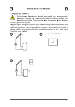
Page 7: ...s and do not claim to be complete The controller does not replace safety devices under any circumstances Depending on the specific application additional system components and safety components may be...

Page 8: ...ing sure not to touch the electronics when doing so 4 Hold the lower part of the hous ing up to the selected position and mark the 3 mounting holes Make sure that the wall surface is as even as possib...

Page 9: ...g connected to the unit must not be stripped by more than 55mm and the cable jacket must reach into the housing just to the other side of the strain relief Relay R1 is only suitable for standard pumps...

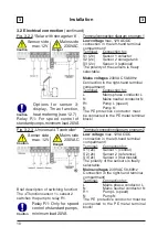
Page 10: ...al conductor N R1 Pump L speed N Pump N The PE protective conductor must be connected to the PE metal terminal block Relay R1 For speed control of standard pumps minimum load 20VA Low voltage max 12VA...

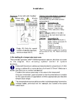
Page 11: ...the specific area of application with the appropriate permissible temperature range Installation Terminalconnectiondiagram program3 Fig 3 2 4 Solar with add heating Low voltage max 12VAC DC connection...

Page 12: ...ntry or to exit a menu If applicable there will be a request for confirmation as to whether the changes which have been made should be saved The function of each of the other three keys 4 is shown in...

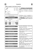
Page 13: ...there Current temperature values with explanations see 6 Function control of the system with operating hours etc see 7 Select graphics mode or overview mode see 8 Automatic mode manual mode or switch...

Page 14: ...ve functions if adaptations are necessary see 11 Menu 7 Special functions if additional changes are necessary see 12 necessary basic settings in the correct order and provides brief descriptions of ea...

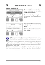
Page 15: ...the measurement value then there may be a defective or incorrect temperature sensor Caution Measurement values menu 1 6 6 If the cables are too long or the sensors are not placed optimally the result...

Page 16: ...tity is activated under 12 7 7 4 Graphic overview menu 2 4 This provides a clearly organised display of the data listed under 7 1 7 3 as a bar graph Various time ranges are available for comparison Th...

Page 17: ...y pressing esc or selecting Exit display mode 8 1 Schematic menu 3 1 In graphics mode the selected hydraulic systems are depicted with the measured temperatures and operating states of the connected c...

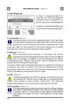
Page 18: ...unction control 9 2 Manual menu 4 2 9 3 Off menu 4 3 When the operating mode Off is activated all controller functions are switched off This can lead for example to overheating on the solar collector...

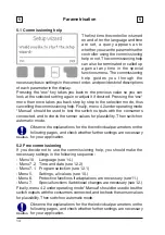
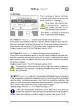
Page 19: ...nsor 2 falls below this value again and the other conditions are also met then the controller switches the pump on again Setting range from 0 C to 99 C default setting 60 C Settings menu 5 10 10 Cauti...

Page 20: ...heating at relais 2 is deactivated If the Energy saving mode is active 10 6 the system heats up until TminS3 hysteresis temperature is reached Setting range from 2 C to 20 C default setting 10 C 10 6...

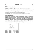
Page 21: ...d off Setting range from 00 00 to 23 59 default setting 06 00 to 22 00 10 9 Party function With the party function the storage temperature is heated up once to the reference temperature TrefS3 respect...

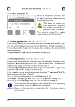
Page 22: ...11 2 Frost protection menu 6 2 6 2 1 6 2 2 A two stage frost protection function can be activated In stage 1 the controller switches the pump on for 1 minute every hour if the collector temperature dr...

Page 23: ...when the solar pump is on a warning or error message is triggered The red light flashes and the corresponding warning appears in the display Col alarm setting range Off 60 C to 300 C default setting...

Page 24: ...ivery Whenever heating up has been carried out with the anti Legionella function switched on an information message with the date appears on the display that the energy source allows this AL function...

Page 25: ...ction can lead to unpredictable errors For analysis of the system data it is essential for the time to be set accurately on the controller Please note that the clock does not continue to run if the ma...

Page 26: ...ions for the the individual parameters in these instructions and check whether further settings are necessary for your application 12 6 Expansions menu 7 6 This menu can only be selected and used if a...

Page 27: ...This function should only be activated by a specialist if problems arise with acquisition of measurement values In particular follow the instructions from the collector manufacturer Special functions...

Page 28: ...the set value then the pump is switched off Variant V2 After the purging time the controller switches to the set min speed If the temperature difference T between sensor 1 and sensor 2 is greater tha...

Page 29: ...in speed menu 7 9 5 12 9 6 Setpoint menu 7 9 6 The maximum speed of the pump at relay R1 is specified here During the setting the pump runs at the specified speed and the flow rate can be determined S...

Page 30: ...necessary 1 Measurement values 2 Analysis 3 Display mode 7 2 Time date 8 Menu lock 9 Service values To lock the other menus select Menu lock on To enable the menus again select Menu lock off Setting...

Page 31: ...s at the time when the error occurs e g in the table The menu can be closed at any time by pressing esc 9 1 9 2 9 3 9 4 9 5 9 6 9 7 9 8 9 9 9 10 9 11 9 12 9 13 9 14 9 15 9 16 9 17 9 18 9 19 9 20 9 21...

Page 32: ...me date Notes for the specialist Means that either the sensor the sensor input at the controller or the connecting cable is was defective Resistance table on page 5 Means that the collector has fallen...

Page 33: ...re working on the unit switch off the power supply and secure it against being switched on again Check for the absence of power Danger Danger Only use the supplied spare fuse or a fuse of the same des...

Page 34: ...proven and successful method for remote diagnosis Write the service values down see 15 at the time that the suspected malfunction occurs Send the service value table by fax or e mail with a brief desc...

Page 35: ...35 Notes...
Page 36: ...kh vel Tel 49 0 2339 6024 Fax 49 0 2339 6025 www sorel de info sorel de Final declaration Although these instructions have been created with the greatest possible care the possibility of incorrect or...

Reviews: