background image

TDC 3

Temperature-Difference-Controller

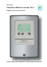
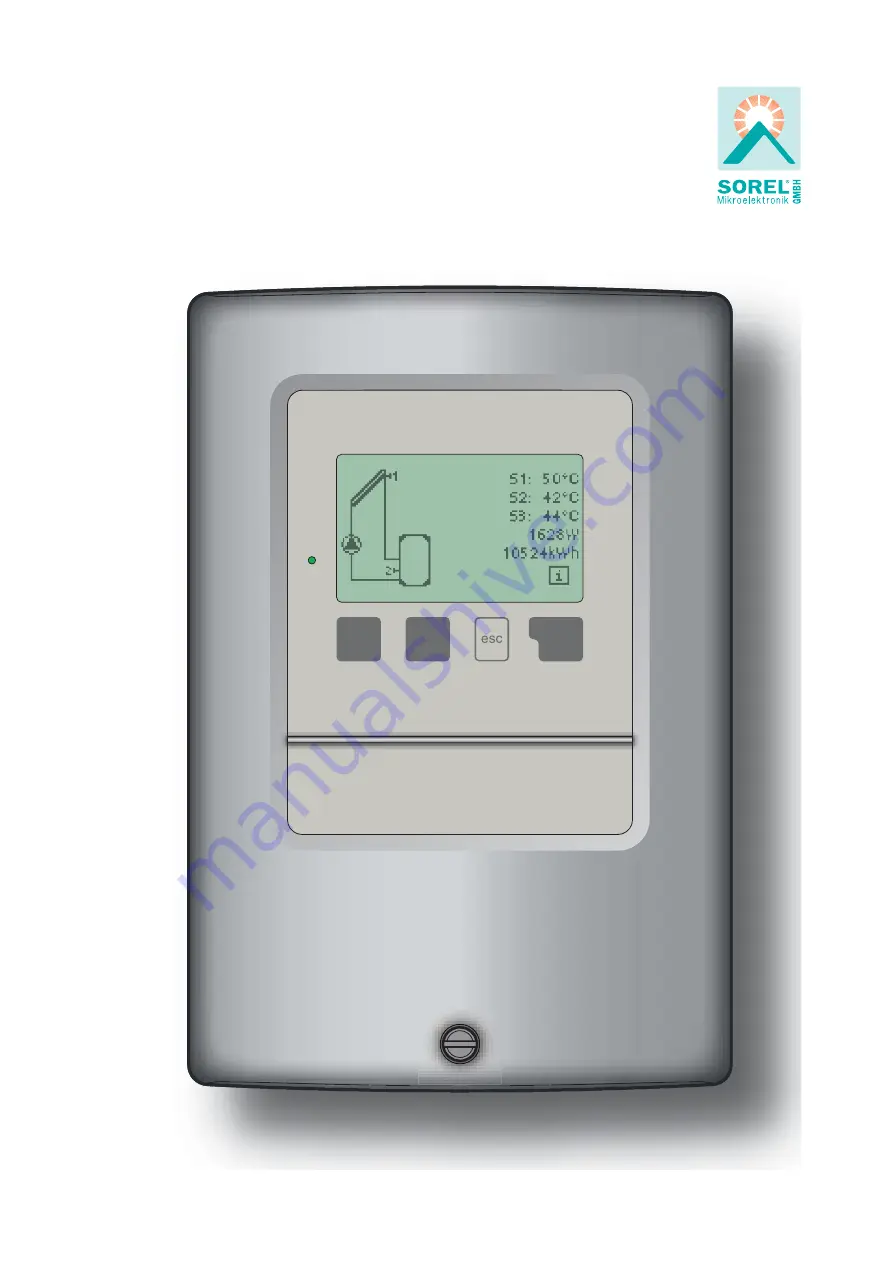
Temperature Difference Controller TDC 3

Installation and operating instructions

115V Version

Read carefully before installation, commissioning and operation

Summary of Contents for TDC 3

Page 1: ...TDC 3 Temperature Difference Controller Temperature Difference Controller TDC 3 Installation and operating instructions 115V Version Read carefully before installation commissioning and operation ...

Page 2: ... 13 38 Language menu10 14 38 Malfunctions maintenance 16 1 Error messages 16 2 Replacing the fuse 16 3 Maintenance 16 40 41 41 Installation 3 1 Wall installation 3 2 Electrical connection 3 3 Installing the sensors 3 8 9 17 17 30 30 31 32 32 Special functions menu 7 12 1 Program selection 12 2 Time date 12 3 Sensor calibration 12 4 Commissioning 12 5 Factory settings 12 6 Expansions 12 7 Heat mete...

Page 3: ...E regulations the regulations of the local power utility the applicable DIN EN standards and the installation and operating instruction of the additional system components must also be observed The controller does not under any circumstances replace any safety devices to be provided by the customer Installation electrical connection commissioning and maintenance of the unit may only be carried out...

Page 4: ... use original spare parts and accessories Use of the device for other than its intended purpose Operation above or below the limit values listed in the specifications Force majeure Changes additions to or conversion of the unit are not permitted without the written permission from the manufacturer It is likewise forbidden to install additional components that have not been tested together with the...

Page 5: ...condensation permitted Other specifications and dimensions Housing design 2 part ABS plastic Installation methods Wallinstallation optionallypanel installation Overall dimensions 163mm x 110mm x 52mm Aperture installation dimensions 157mm x 106mm x 31mm Display Fully graphical display 128 x 64 dots Light diode Multicolour Operation 4 entry keys Temperature sensors may not be included in the scope ...

Page 6: ...Menu block can be activated to prevent unintentional setting changes Resetting to previously selected values or factory settings A wide range of additional functions are available Description of controller 2 2 2 3 Scope of supply Temperature Difference Controller TDC 3 3 screws 3 5x35mm and 3 plugs 6mm for wall installation 6 strain relief clips with 12 screws replacement fuse 2A slow blow Install...

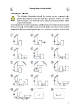
Page 7: ...laim to be complete The controller does not replace safety devices under any circumstances Dependingonthespecificapplication additionalsystemcomponentsandsafety componentsmaybemandatory suchascheckvalves non returnvalves safety temperature limiters scalding protectors etc and must therefore be provided Caution 1 3 5 2 4 7 10 13 6 8 9 11 12 14 T controller 15 2x T controller T 2x T ...

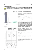
Page 8: ... being sure not to touch the electronics when doing so 4 Hold the lower part of the housing up to the selected position and mark the 3 mounting holes Make sure that the wall surface is as even as possible so that the housing does not become distorted when it is screwed on 5 Using a drill and size 6 bit drill 3 holesatthepointsmarkedon the wall and push in the plugs 6 Insert the upper screw and scr...

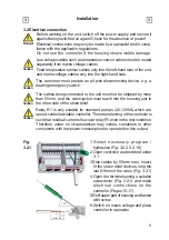
Page 9: ...nected to the unit must not be stripped by more than 55mm and the cable jacket must reach into the housing just to the other side of the strain relief Relay R1 is only suitable for standard pumps 20 120VA which are speed controlled viathe controller The internal wiring of the controller is such that residual currents flow over relay R1 even in the rest condition Therefore under no circumstances ma...

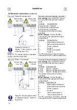
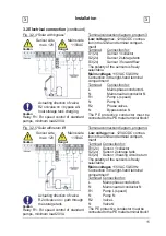
Page 10: ...e conductor must be connected to the PE metal terminal block Sensor side max 12V Danger Caution Mains side 115VAC Fig 3 2 2 Solar with storage tank Terminal connection diagram program 1 Low voltage max 12VAC DC connec tion in the left hand terminal compart ment Sensor side max 12V Danger Caution Mains side 115VAC Caution Options for sensor 3 display Tmax function heat metering see 12 7 Terminal Co...

Page 11: ...rotective conductor must be connected to the PE metal terminal block Relay R1 For speed control of standard pumps minimum load 20VA Fig 3 2 5 Solar with return lift Terminal connection diagram program 4 Low voltage max 12VAC DC connec tion in the left hand terminal compart ment Terminal Connection for S1 2x Sensor 1 collector S2 2x Sensor 2 storage tank S3 2x Sensor 3 heating circuit return The po...

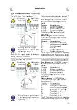
Page 12: ...l terminal block Relay R1 For speed control of standard pumps minimum load 20VA Actuating direction of valve R2 on valve on charge to sen sor 3 storage tank above Terminal connection diagram program 6 Fig 3 2 7 Solar with ext heat exchanger Low voltage max 12VAC DC connec tion in the left hand terminal compart ment Terminal Connection for S1 2x Sensor 1 collector S2 2x Sensor 2 storage tank S3 2x ...

Page 13: ...E metal terminal block Relay R1 For speed control of standard pumps minimum load 20VA Actuating direction of valve R2 on valve on collector with flow through sensor 3 Terminal connection diagram program 8 Fig 3 2 9 Solar 2 coll 2 pumps Low voltage max 12VAC DC connec tion in the left hand terminal compart ment Terminal Connection for S1 2x Sensor 1 collector 1 S2 2x Sensor 2 storage tank S3 2x Sen...

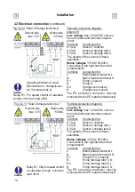
Page 14: ...umps minimum load 20VA Actuating direction of valve R2on valveon charge to sen sor 3 storage tank 2 Terminal connection diagram program 10 Fig 3 2 11 Solar 2 storage tank 2 pu Low voltage max 12VAC DC connec tion in the left hand terminal compart ment Terminal Connection for S1 2x Sensor 1 collector S2 2x Sensor 2 storage tank 1 S3 2x Sensor 3 storage tank 2 The polarity of the sensors is freely s...

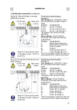
Page 15: ...ductor must be connected to the PE metal terminal block Terminal connection diagram program 12 Fig 3 2 13 Solar with swimming pool and heat exchanger Low voltage max 12VAC DC connec tion in the left hand terminal compart ment Terminal Connection for S1 2x Sensor 1 collector S2 2x Sensor 2 swimming pool S3 2x Sensor 3 forward flow The polarity of the sensors is freely Caution Relay R1 Only for spee...

Page 16: ...um load 20VA Actuating direction of valve R2 on valve on charge to sen sor 3 swimming pool Terminal connection diagram program 14 Fig 3 2 15 Universal T controller Low voltage max 12VAC DC connec tion in the left hand terminal compart ment Terminal Connection for S1 2x Sensor 1 control S2 2x Sensor 2 reference S3 2x Sensor 3 thermostat The polarity of the sensors is freely Caution Relay R1 Only fo...

Page 17: ...Brief description of switching function The T function sensor 1 sensor 2 switches the pump to relay R1 The T function 2 sensor 3 switches the pump to relay R2 Installation 3 3 3 2 Electrical connection continued 3 3 Installing the temperature sensors The temperature sensor cables must be routed separately from mains voltage cables and must not for example be routed in the same cable duct Caution T...

Page 18: ...is used to cancel an entry or to exit a menu If applicable there will be a request for confirmation astowhetherthechangeswhichhave been made should be saved The function of each of the other three keys 4 is shown in the display line directly above the keys the right hand keyisgenerallyhasaconfirmationand selection function Examples of key functions enlarge shrink values scroll menu down up yes no ...

Page 19: ...here Current temperature values with explanations see 6 Function control of the system with operating hours etc see 7 Select graphics mode or overview mode see 8 Automatic mode manual mode or switch unit off see 9 Set parameters needed for normal operation see 10 Solar and frost protection recooling anti seizing protection see 11 Program selection sensor cali bration clock additional sensor etc se...

Page 20: ... see 10 Menu 6 Protective functions if adaptations are necessary see 11 Menu 7 Special functions if additional changes are necessary see 12 thecorrectorder andprovidesbriefdescriptionsofeachparameterinthedisplay Pressing the esc key takes you back to the previous value so you can look at the selected setting again or adjust it if desired Pressing the esc more than once takes you back step by step ...

Page 21: ... the measurement value then there may be a defective or incorrect temperature sensor Caution Measurement values menu 1 6 6 If the cables are too long or the sensors are not placed optimally the result may be small deviations in the measurement values In this case the display values can be compensated for by making entries on the controller Follow the instructions under 12 3 What measurement values...

Page 22: ...menu 2 4 This provides a clearly organised display of the data listed under 7 1 7 3 as a bar graph Various time ranges are available for comparison The two left hand keys can be used to page through the data 7 5 Error messages menu 2 5 Resettinganddeletingtheindividualanalyses Thefunction Allstatistics clears all analyses but not the error messages 7 6 Reset clear menu 2 6 Display of the last thre...

Page 23: ... menu 3 1 In graphics mode the selected hydraulic systems are depicted with the mea sured temperatures and operating states of the connected consumers 8 4 Temperature Unit menu 3 4 The controllers temperature unit can be switched between Celsius and Fahr enheit Select the unit here 8 2 Overview menu 3 2 In overview mode the measured temperatures and operating states of the connected consumers are ...

Page 24: ...control 9 2 Manual menu 4 2 9 3 Off menu 4 3 When the operating mode Off is activated all controller functions are switched off This can lead for example to overheating on the solar collector or other system components The measured temperatures Automatic mode is the normal operating mode of the controller Only automatic mode provides proper controller function taking into account the current tempe...

Page 25: ...s the associated pump and or valve on If the temperature at sensor 1 drops below this value by 5 C then the pump and or the valve are switched off again Setting range from 0 C to 99 C default setting 20 C 10 2 Tmin S2 menu 5 x enable start temperature at sensor 2 If this value is exceeded at sensor 2 and the other conditions are also met then the controller switches the associated pump and or valv...

Page 26: ... 5 x switch off temperature at sensor 3 If this value is exceeded at sensor 3 and the other conditions are also met then the controller switches the associated pump and or valve off If sensor 3 falls below this value again and the other conditions are also met then the controller switches the pump and or valve on again Setting range from 0 C to 99 C default setting 60 C 10 6 T R1 menu 5 x switch o...

Page 27: ...at sensor 3 has risen to Tsetpoint S3 plus the hysteresis If the temperature at sensor 3 exceeds this value and a negative value is set under Hysteresis thenrelayR2switchesonas aheatdissipationfunction The heat dissipation function remains active until the temperature at sensor 3 has fallen to Tsetpoint S3 minus the hysteresis Setting range from 0 C to 99 C default setting 60 C 10 8 Tsetpoint S3 m...

Page 28: ...at will soon enable charging in the higher priority storage tank If the conditions for charging the higher priority storage tank or for continued interruption are not met then the charging of the lower priority storage tank is enabled again and interrupted again after the time set here in order to consider the current temperature increase of the collector Setting range from 5 to 90 minutes default...

Page 29: ...S1 R1 S1 R1 S1 R1 S1 R1 R2 S1 R1 S1 R1 S1 R1 S1 R1 S1 R1 Tmin S2 S2 R2 S2 R2 S2 R2 Tmin S3 S3 R1 R2 S3 R2 Tmax S2 S2 R1 R2 S2 R1 S2 R1 R2 S2 R1 S2 R1 S2 R1 R2 S2 R1 R2 S2 R1 R2 S2 R1 S2 R1 S2 R1 S2 R1 R2 S2 R1 S2 R1 S2 R1 Tmax S3 S3 R2 S3 R1 R2 S3 R1 R2 S3 R2 S3 R2 S3 R1 R2 S3 R2 T R1 S1 S2 R1 R2 S1 S2 R1 S1 S2 R1 S3 S2 R2 S1 S2 R1 S1 S2 R1 S1 S3 R1 R2 S1 S2 R2 S3 S2 R1 S1 S2 R1 S3 S2 R1 R2 S1 S2 ...

Page 30: ...R2 daily weekly off default setting daily 11 2 Frost protection menus 6 2 6 2 1 6 2 2 A two stage frost protection function can be activated In stage 1 the controller switches the pump on for 1 minute every hour if the collector temperature drops below the set value Frost stage 1 If the collector temperature drops further to the set value Frost stage 2 the con troller switches the pump on continuo...

Page 31: ... triggered The red light flashes and the corresponding warning appears in the display Col alarm setting range Off 60 C to 300 C default setting Off SPF variant V1 If the value SPF T on is exceeded at the collector the pump is switched on to cool the collector The pump is switched off if the value at the collector drops bellow SPF T off or the value SPF Tmax stor is exceeded at the storage tankorsw...

Page 32: ...ery Thisfunctionisonlyrelevantforstoragetankswheresensor2isinstalled Whenever heating up has been carried out with the anti Legionella function switched on an information message with the date appears on the display AL Tsetpoint S2 setting range from 60 C to 99 C default setting 70 C AL frequency setting range from 1 to 28 days default setting 7 days AL Heat Shows the last time the AL function was...

Page 33: ...program selection can lead to unpredictable errors For analysis of the system data it is essential for the time to be set ac curately on the controller Please note that the clockdoesnotcontinueto runifthemainsvoltageisinterrupted andmustthereforebereset Caution 12 3 Sensor calibration menus 7 3 7 3 1 7 3 3 Deviationsinthetemperaturevaluesdisplayed forexampleduetocableswhich are to long or sensors ...

Page 34: ...ring commissioning Observe the explanations for the the individual parameters in these instructions and check whether further settings are necessary for your application 12 6 Expansions menu 7 6 This menu can only be selected and used if additional options or expansions have been built into the controller Theassociatedsupplementaryinstallation mountingandoperationinstructions are then included wit...

Page 35: ...hould only be activated by a specialist if problems arise with acquisition of measurement values In particular follow the instruc tions from the collector manufacturer Special functions menu 7 12 12 AF type menu 7 7 2 Adjust the type of glycol that has been used in the system Settings range Ethylene Propylene default setting Ethylene Glycol portion menu 7 7 3 Adjust the percentage of glycol that h...

Page 36: ...f the set value then the pump is switched off Variant V2 After the purging time the controller switches to the set min speed If the temperature difference T between the reference sensors collector and storage tank is greater than the set value then the speed is increased by one stageafterthecontroltimeelapses Ifthetemperaturedifference Tbetweenthe reference sensors is below the set value then the ...

Page 37: ...Min speed menu 7 9 5 12 9 6 Setpoint menu 7 9 6 The maximum speed of the pump at relay R1 is specified here During the set ting the pump runs at the specified speed and the flow rate can be determined Setting range from 70 to 100 default setting 100 The indicated percentages are guide values that may vary to a greater or lesser extent depending on the system pump and pump stage Caution Theminimums...

Page 38: ... if necessary 1 Measurement values 2 Analysis 3 Display mode 7 2 Time date 8 Menu lock 9 Service values To lock the other menus select Menu lock on To enable the menus again select Menu lock off Setting range on off default setting off Language menu 10 14 14 Menu 10 Language can be used to select the language for the menu guidance Thisisqueriedautomatically during initial commissioning The choice ...

Page 39: ...es The menu 9 Service values can be usedforremotediagnosisbyaspecial ist or the manufacturer in the event of an error etc Caution Enter the values at the time when the error occurs e g in the table The menu can be closed at any time by pressing esc ...

Page 40: ...Time date Notes for the specialist Means that either the sensor the sensor input at the controller or the connecting cable is was defective Resistance table on page 5 Means that the collector has fallen fell below the temperature set under menu 6 3 1 Means that the solar pump is was in operation between 23 00 and 04 00 Exception see 11 4 Means that the controller was restar ted forexampleduetoapow...

Page 41: ...g on the unit switch off the power supply and secure it against being switched on again Check for the absence of power Danger Danger Only use the supplied spare fuse or a fuse of the same design with the following specifications T2A 250V Fig 3 1 1 Fuse 16 3 Maintenance In the course of the general annual maintenance of your heating sys tem you should also have the functions of the controller check...

Page 42: ...successfulmethodforremotediagnosis Write the service values down see 15 at the time that the suspected malfunction occurs Send the service value table by fax or e mail with a brief description of the error to the specialist or manufacturer Inprogram13 Solarwithstoragetankandpool thechargingofthepool e g for winter operation can be switched off using a simple function Todothis simplypressandholdthe...

Page 43: ...rn lift etc Useful notes tips and tricks 17 17 The Operating hours displayed in the Analysis menu are solar ope rating hours This therefore only takes into account hours in which the solar pump is active In the universal programs 14 15 the times refer to relay R1 To protect against loss of data record any analyses and data that are particularly important to you see7 at regular intervals ...

Page 44: ...lityofincorrectorincompleteinformationcannotbeexcluded Subject as a basic principle to errors and technical changes Notes Hydraulic variant set Commissioned on Commissioned by Your specialist dealer Manufacturer SOREL GmbH Mikroelektronik Jahnstr 36 D 45549 Sprockhövel Tel 49 0 2339 6024 Fax 49 0 2339 6025 www sorel de info sorel de ...

Reviews: