Sorensen MML Series Operation and Programming Manual
7-4
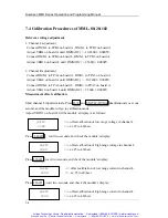
7.4 Calibration Procedures of MML-80-20-102
Reference voltage adjustment
:
1. Channel L adjustment
Connect DMM+ to TPB4 on board A , DMM
−
to TPB3 on board A.
Adjust VRB4 on board A until DMM (DC) =
−
10.2400
±
0.0005V.
Connect DMM+ to TPB6 on board L, DMM
−
to TPB3 on board A.
Adjust VRB10 on board L until DMM (DC) = 2.5600
±
0.0002V.
2. Channel R adjustment
Connect DMM
+
to TPA4 on board A, DMM
−
to TPA3 on board A.
Adjust VRA4 on board A until DMM (DC) =
−
10.2400
±
0.0005V.
Connect DMM
+
to TPA6 on board L, DMM
−
to TPA3 on board A.
Adjust VRA10 on board L until DMM (DC) = 2.5600
±
0.0002V.
Measurement offset calibration
:
Short channel L input terminals. Press R-/L and STATIC/DYNA simultaneously over one
second, and the module will go to calibration mode.
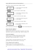
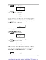
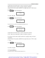
Adjust VRB11 on board L till the module’s display is as follows:
LoFFS
<<
−
offset calibration of low range voltage in channel L
00XX
<<
−
xx:25 to 40(hex)
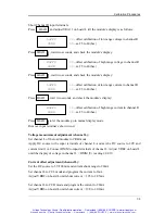
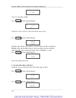
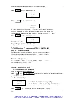
Press LOAD , wait two seconds, and check the module’s display:
HoFFS
<<
−
offset calibration of high range voltage in channel L
00XX
<<
−
xx:25 to 40(hex)
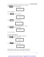
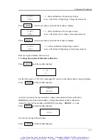
Press LOAD , wait two seconds, and check the module’s display:
LoFFS
<<
−
offset calibration of low range current in channel L
00XX
<<
−
xx:25 to 40(hex)
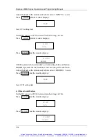
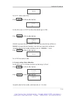
Press LOAD , wait two seconds, and check the module’s display:
HoFFS
<<
−
offset calibration of high range current in channel L
00XX
<<
−
xx:25 to 40(hex)
Artisan Scientific - Quality Instrumentation ... Guaranteed | (888) 88-SOURCE | www.artisan-scientific.com
Artisan Technology Group - Quality Instrumentation ... Guaranteed | (888) 88-SOURCE | www.artisantg.com

