Calibration Procedures
7-23
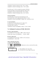
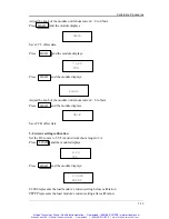
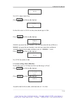
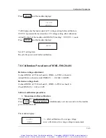
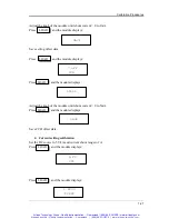
Press LOAD and the module displays:
76.000
UUUUU
76.000 represents the load module’s CV voltage setting before calibration.
UUUUU represents the load module’s CV voltage setting after calibration.
Adjust the knob of the module until DMM (V) reading = UUUUU
±
1 count.
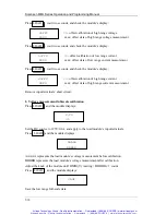
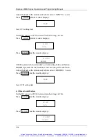
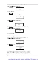
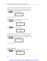
Press LOAD and the module displays:
SAvE
Save CV setting data.
Recycle the power switch after calibration.
7.8 Calibration Procedures of MML-500-20-601
Reference voltage adjustment:
Connect DMM+ to TPA4 on board A, DMM
−
to TPA3 on board A.
Adjust VRA4 on board A until DMM (V) =
−
10.2400
±
0.0005V.
Reference voltage check:
Connect DMM+ to TPA6 on board L, DMM
−
to TPA3 on board A.
Check DMM (V) = 2.48 to 2.60V.
Software calibration procedures
1. Measurement offset calibration
Short the module’s input terminals of
+
,
−
.
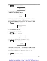
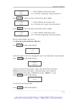
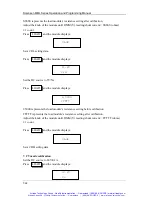
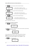
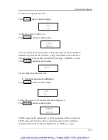
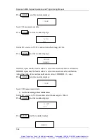
Press A/B and STATIC/DYNA simultaneously over one second to let the module
go to calibration mode.
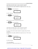
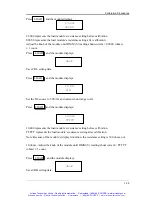
The module displays:
LoFFS
<<
−
offset calibration of low range voltage
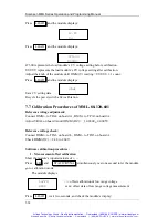
XXXX
xxxx: offset data of low range voltage measurement
Artisan Scientific - Quality Instrumentation ... Guaranteed | (888) 88-SOURCE | www.artisan-scientific.com
Artisan Technology Group - Quality Instrumentation ... Guaranteed | (888) 88-SOURCE | www.artisantg.com

