Local Operation
4-17
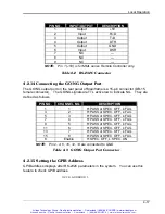
PIN NO.
INPUT/OUTPUT
DESCRIPTION
1
Output
+
5V
2 Input R
×
D
3 Output T
×
D
4 Output DTR
5 Output GND
6 Input DSR
7 NC
—
8 NC
—
9 NC
—
NOTE:
Pin 1 (
+
5V) is for MML series Remote Controller only.
Table 4-2 RS-232C Connector
4.2.14 Connecting the GO/NG Output Port
The GO/NG output port on the rear panel of Mainframe is a 15-pin connector (DB-15,
female connector). The GO/NG signals are TTL active low to indicate NG. They are
defined as follows.
PIN NO.
CHANNEL NO.
DESCRIPTION
1
1
H:PASS or SPEC. OFF, L:FAIL
3
2
H:PASS or SPEC. OFF, L:FAIL
5
3
H:PASS or SPEC. OFF, L:FAIL
7
4
H:PASS or SPEC. OFF, L:FAIL
9
5
H:PASS or SPEC. OFF, L:FAIL
11
6
H:PASS or SPEC. OFF, L:FAIL
13
7
H:PASS or SPEC. OFF, L:FAIL
15
8
H:PASS or SPEC. OFF, L:FAIL
8
Enable
H:SPEC. OFF, L:SPEC. ON
NOTE:
Pin 2, 4, 6, 10, 12, 14 are connected to GND.
Table 4-3 GO/NG Output Port Connector
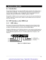
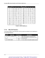
4.2.15 Setting the GPIB Address
GPIB address displays after RS-232C parameters in the system. You can use this
feature to check GPIB address.
GPIB ADDRESS 1
Artisan Scientific - Quality Instrumentation ... Guaranteed | (888) 88-SOURCE | www.artisan-scientific.com
Artisan Technology Group - Quality Instrumentation ... Guaranteed | (888) 88-SOURCE | www.artisantg.com

