background image

service record Airon

1 von 36

2021-06-10

Besondere Menschen, besondere Lösungen.

de

Unique people, unique solutions.

Service record Airon

Service record

Service record

All individual adjustments to the wheelchair are described 

below

. Tools and specialist knowledge are required for these 

settings. Please leave these adjustments to a qualified 

rehabilitation specialist. 

Airon

Airon

EN

Summary of Contents for Airon

Page 1: ...people unique solutions Service record Airon Service record Service record All individual adjustments to the wheelchair are described below Tools and specialist knowledge are required for these settin...

Page 2: ...The handling is to be carried out accordingly Gender notice For editorial reasons for better readability only the masculine form is used Correspon ding terms apply in the sense of equal treat ment to...

Page 3: ...panels 18 3 4 2 Clothes guard on the side panel 18 3 4 3 Armrest on the side part standard 19 3 4 4 Height adjustment of the plug in side panel 19 3 5 Brakes assembly 20 3 5 1 General information on t...

Page 4: ...n 1 Push handles 2 backpart with cushion 3 clothes guards 4 side panel 5 seat cushions 6 protective pads 7 utensil pocket 8 frame 9 caster wheel fork 10 caster wheel 11 foot plate continuous 12 drive...

Page 5: ...or comments please contact your specialist retailer or our team 49 7254 9279 0 2 2 Documentation notes Please note Information for the user can be found in the instructions for use Maintenance instru...

Page 6: ...ng Set or adjust the angle open close Turn clockwise Turn counterclockwise Steps to be performed at the same time Steps to be performed in se quence Steps to be performed on both sides Handling A B 1...

Page 7: ...e repla ced with new ones Only regular maintenance of all safety relevant parts on the wheelchair by a qualified rehab workshop protects against damage and maintains our manufacturer s warranty Lifesp...

Page 8: ...and out The further you mount the drive wheels with the perforated plate to the front the greater the risk of the wheelchair tipping backwards D 1 3 1 2 Seat height in front 2 A B 2 The front seat he...

Page 9: ...the clamping flange to the desi red holes 2B attach the screws and threaded sleeves and tighten all screws again Mount the side parts and put the drive wheels back into the quick release axle The clam...

Page 10: ...d 1B2 Loosen the threaded pins 1D1 and 1D2 pull out the adapter After replacing insert the caster wheel adapter into the adapter mount Tighten the threaded pins 1D1 and 1D2 again Reinstall the screws...

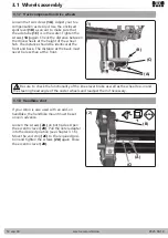
Page 11: ...that there is sufficient distance to the side panel so that the drive wheel does not touch the side panel when it is loaded from the side After every change to the camber adap ter it must be checked...

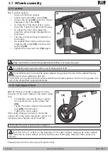
Page 12: ...he front 3 1 7 Track compensation drive wheels 3 1 Wheels assembly A Be sure to check the functionality of the knee lever brake as well as the wheel toe in and the steering head angle of the caster wh...

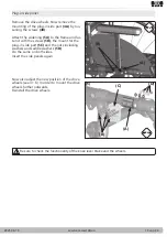
Page 13: ...eelbase extension 2A to the desired position on the drive wheel mount 3A on both sides Make sure that the same holes are used on both sides of the drive wheel mount 3A Now fasten the screws 3B on both...

Page 14: ...ed hole A 1 B B 3 2 2 Seat width growth The seat width can be widened by adding distances of 1 cm per side Standard side panel Remove the drive wheels Now remove the side parts by loosening the screws...

Page 15: ...d fas ten it with the screws 5B the mount for the plug in side part 5C and the nuts including washers and saddle washers 5D Do the same on both sides Insert the side panels again A A C Now also adjust...

Page 16: ...seat molding up to a finger s breadth in front of the hollow of the knee Model 1 Standard Model 2 Can be folded up to the side Model 3 Can be folded up to the side and tur ned away to the outside Mode...

Page 17: ...verse order Angle adjustment Loosen the countersunk head screws 1A and set the desired angle Tighten the countersunk screws 1A again A 1 3 3 4 Standard leg support for short lower leg lengths Adjustin...

Page 18: ...rmly The distance between the top of the wheel and the clothes guard should be at least 10 mm so that the clothes guard does not touch the wheel when it is under load 3 4 2 Clothes guard on the side p...

Page 19: ...tighten them tightly 2 3 To change the height of the plug in side panel remove the screw with the correspon ding sleeve A and put it in a desired hole C and tighten the screw and sleeve A again In ord...

Page 20: ...eels in a rest position They are not desi gned to slow down the wheelchair while it is in motion The correct functioning of the brakes can be impaired by tire pressure too low Wetness dirt snow ice et...

Page 21: ...2A The brake cable is re tensioned by turning the adjusting screw counterclockwise The brake shoes of the drum brake are very sensitive to dirt lint etc Clean the brake body regularly with a dry brush...

Page 22: ...desired hole 1B and tighten it A B C 1 The anti tipper are set at the factory If the setting is to be changed this can be done by moving the stand tube The tilt protection can also be changed by mo vi...

Page 23: ...ve the camber adapter 1D by loose ning the screws 1E 1F 4 Mount the retaining plate of the anti tipper on the axle unit 2A 5 Now mount the clamping flange on the axle 3A 6 Pull the complete axle unit...

Page 24: ...the tilt bracket 1A from below into the drive wheel mounting tube and bring it to the desired height screw it tight with the screws 1B in the drive wheel mounting tube It is not possible to mount the...

Page 25: ...back cover 3A back over the Velcro fasteners and close at the lower edge When using a stabilizing bar the slack in the back covering must not be so great that the back comes into contact with the stab...

Page 26: ...recess 6C With the help of these discs you can fine tune the back angle in 4 steps To do this insert either 0 insert 3A or 4 insert 3B into the recess 6C If the insert 0 is in serted the angles 78 90...

Page 27: ...e hole 1B on the front re esta blish all screw connections and tighten firmly 3 8 Back assembly B 3 8 6 Replacing removing the moulded back plate 2 When widening the seat you must first remove the old...

Page 28: ...ongue 3B with the two screws 3C 3 On the other hand the pads can be adjus ted by moving the C rail 3D on the back tube holder If necessary loosen the two screws 3B and thread the pad holder 3A out of...

Page 29: ...crews A into the metal tongue picture 3C previous page adjust the height tighten the screws A again 2 On the other hand it can be done by mo ving the pad Remove the covers loosen the screws 2A move th...

Page 30: ...elchair and all components with a mild household cleaning agent on a water basis and then dry it thoroughly In addition clean the drive and caster wheels and remove dirt and contamination e g hair etc...

Page 31: ...he specialist trade as is the reusability Use beyond the specified service life leads to an increase in the residual risks and should only be carried out after careful qualified consideration by the o...

Page 32: ...re tread the firm fit of third party systems if available Perform a cleaning and oil all moving parts Inadequate or neglected maintenance of the wheelchair represents a significant safety risk Mainten...

Page 33: ...hand rim size at 24 max 538 mm hand rim size at 25 565 mm Diameter hand rim 19 mm Pipe diameter camber 1 3 5 7 With drum brake wheels seat height SH front min 380 mm The seat heights are measured from...

Page 34: ...the relevant provisions of the EU Regulation EU 2017 745 on medical products This was verified by a conformity assessment procedure in accordance with the provisions for medical products This declarat...

Page 35: ...service record Airon 35 von 36 2021 06 10 6 Notes...

Page 36: ...lstuhltechnik GmbH Co KG Benzstra e 3 5 68794 Oberhausen Rheinhausen Germany Fon 49 7254 9279 0 Fax 49 7254 9279 10 info sorgrollstuhltechnik de www sorgrollstuhltechnik de company stamp Service recor...

Reviews: