6
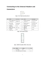
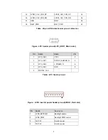
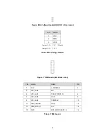
Figure : Front Panel Connector(J_FIO_1)
PIN
NAME
Description
PIN NAME
Description
1
HDD_POWER_LED
(Orange color)
Pull-up resistor
(330Ω) to +5V
2
POWER_LED_MAIN
(Green color)
[Out] Front panel
LED (Green)
3
HDD_LED#
(Orange color)
[Out] Hard disk
activity LED
4
POWER_LED_ALT
(Green color)
[Out] Front panel
LED (Yellow)
5
GROUND
(Blue color)
Ground
6
POWER_SWITCH#
(Red color)
Power button
7
RESET_SWITCH#
(Blue color)
Reset switch
8
GROUND
(Red color)
Ground
9
+5V_DC
(Black color)
Power
10
KEY
(Black color)
No pin
Table : Front Panel Connector
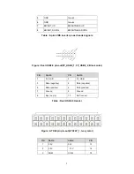
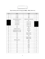
Figure : USB3.0 header(FP_USB3_1, Blue color)
PIN
NAME
NAME
PIN
1
5V_USB31
NA
2
PCH_USB31RX_5N 5V_USB32
19
Summary of Contents for sMB-Q370
Page 1: ...sMB Q370 embedded Motherboard Product Guide www sotm audio com Rev 1 1c...
Page 2: ......
Page 6: ...4 TABLE 2 SOtM sMB Q370 COMPONENTS SHOWN IN FIGURE 1...
Page 21: ...19 sMB Q370 embedded Motherboard BIOS Specification...
Page 78: ...76...
Page 79: ......
Page 80: ...www sotm audio com...

