background image

552 User Guide and Technical Information 

6

v. 1.4 

Features and specifications are subject to change. Visit www.sounddevices.com for the latest documentation.

Quic

ks

tar
t

13) 

Adjust LED Meter brightness. 


Press and hold the Battery Check button while turning the Headphone Controller. 

14) 

Check Internal and External power levels. 


Press the Battery Check 

 button to display the internal and external power levels 

on the Output Meter LEDs. The internal AA battery level is displayed on the left 

meter and external DC voltage level is displayed on the right meter.

15) 

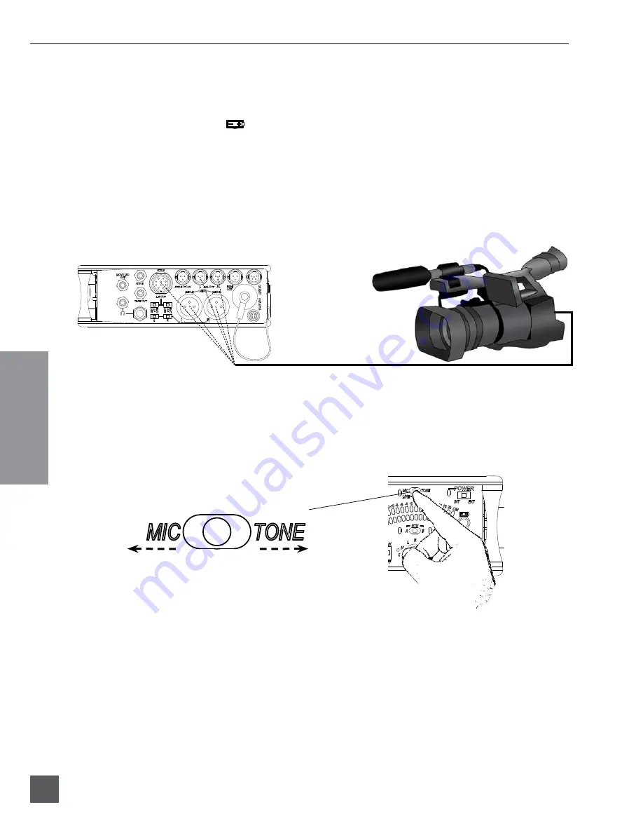
Connect the 552 analog outputs to the next device in the signal chain (audio 

recorder, wireless transmitter, or camera).


Output levels are set (Line, -10, Mic) using the respective output’s attenuation 

switch.  

552 Right Panel

16) 

Set the next device’s input sensitivity to receive the supplied signal.


17)


Activate the 552’s Tone Generator.


Slide the SLATE MIC/TONE switch to the TONE position. Tone latches on if the 

switch is held for two seconds; slide right again to turn off. A 1 kHz tone is gener-

ated and is sent out at 0 dB (level and frequency are menu-adjustable).

Slide left for Slate Mic

Slide right for Tone.

18) 

Adjust the input gain on the next device accordingly. 

Summary of Contents for 552

Page 1: ...certain that this package contains the listed items below 1 552 Five Channel Portable Production Mixer with Integrated Recorder 1 Printed User Guide and Technical Information 4 Rubber Bumpers 6 Colored Dots 1 Purchase Registration Card 1 Setup Menu Chart Card 1 Front Panel Shortcuts Card 1 Packing List this sheet February 2014 ...

Page 2: ......

Page 3: ...xer with Integrated Recorder User Guide and Technical Information firmware rev 1 4 Sound Devices LLC E7556 State Rd 23 33 Reedsburg WI USA 1 608 524 0625 fax 1 608 524 0655 Toll Free 800 505 0625 www sounddevices com support sounddevices com ...

Page 4: ......

Page 5: ... Record Pause Time Code Time Code to Track External Time Code Auto Record Playback Metering 29 Meter Ballistics VU Peak Peak Peak Hold Peak VU Peak Hold VU Meter Reference Level Zoom Metering Input Activity LED Headphone Peak LED Headphone Monitoring 31 Headphone Gain Headphone Source Selection Headphone Tones Record Start and Stop Tones Playback Navigation Tones PFL Channel Solo Monitor RTN A and...

Page 6: ...istered trademark of Apple Computer Other product and company names mentioned herein may be the trademarks of their respective owners The sound waves logo is a registered trademark of Sound Devices LLC Limitation of Liability LIMITATION ON SOUND DEVICES LIABILITY SOUND DEVICES LLC SHALL NOT BE LIABLE TO THE PURCHASER OF THIS PRODUCT OR THIRD PARTIES FOR DAMAGES LOSSES COSTS OR EXPENSES INCURRED BY...

Page 7: ...For external powering connect a DC powering source not included to the DC connector on the Right Panel External Power Supply not included AA AA AA AA 2 Connect analog microphone or line sources to the XLR inputs 552 Left Panel 3 Connect headphones to either the 1 4 inch or the 3 5 mm headphone outputs 552 Right Panel 4 Power On the mixer Slide the power switch to the INT position to power the mixe...

Page 8: ...r hold an input s PFL switch then slide the SLATE MIC TONE switch to the right The input s PH LED illuminates blue when phantom power is applied 1 Hold the Input s PFL 2 Slide the SLATE MIC TONE switch right 7 Select a headphone monitor mode using the Headphone Selector Stereo Left and Right Program Right Program Left Program Stereo MS mid side Recording Source Mono summed left and right L R M ST ...

Page 9: ...ke fine level adjustments 11 Route each input to either Left or Right Outputs using the Input Pan Control Push to release the recessed Pan Control Turn counter clockwise to send the input to the Left Output and turn clockwise to send it to the Right Output Once the pan has been set push the Pan Control again to recess the control and remove it from the mixing surface 12 Set High Pass Filters and L...

Page 10: ...voltage level is displayed on the right meter 15 Connect the 552 analog outputs to the next device in the signal chain audio recorder wireless transmitter or camera Output levels are set Line 10 Mic using the respective output s attenuation switch 552 Right Panel 16 Set the next device s input sensitivity to receive the supplied signal 17 Activate the 552 s Tone Generator Slide the SLATE MIC TONE ...

Page 11: ...t The card should glide smoothly into the slot Do not use excessive force when inserting the card and make certain that the electrical contacts are facing downwards Push on the card to remove it 21 Controlling the Integrated Digital Recorder The Recorder Controller is used to initiate the Record Stop Playback Rewind Fast Forward functions as well as to navigate through recorded files Press in to P...

Page 12: ...d again to deactivate For momen tary action hold the switch left for one second or longer The Input Signal Ac tivity LED flashes yellow when an in put s PFL is latched on The Input PFL Switch is also used to make changes to several input settings See Input Setup and Control 5 Input Signal LED Indicates input signal activity LEDs il luminate in various colors and intensi ties to show signal level a...

Page 13: ...ontrols the Integrated Digital Re corder Record Mode is enabled in the Setup Menu When enabled push up to Record press in to Pause Stop push down to Play push left to Rewind push right to Fast Forward See Digital Audio Recorder 17 Record LED Indicates the status of the recording me dia The LED is off when the recorder is in standby mode Flashes yellow when no SD card is inserted Illuminates solid ...

Page 14: ...Ds illuminate in various colors and intensities to indicate the be havior of the return signals Green re turn signal presence Red return signal overload clipping Yellow the monitor return is latched on When time code is active the TA3 input is used exclusively for time code The 3 5 mm jack functions normally See Return 27 RTN A B Switch Two position momentary switch Slide left for RTN A headphone ...

Page 15: ...n Left Panel Connectors and Controls 1 2 1 Analog Inputs Channels 1 5 Transformer balanced analog micro phone or line level inputs 1 5 on XLR connectors Pin 1 Ground pin 2 Hot pin 3 Cold For unbalanced inputs tie pin 1 and pin 3 together ground pin 2 positive Make cer tain phantom power is off when using unbalanced inputs See Input Setup and Control 2 Analog Direct Outputs Balanced direct outputs ...

Page 16: ... Ground pin 2 Left pin 3 Right Time Code wiring pin 1 and 3 ground pin 2 Hot See Time Code 7 TA3 Master Outputs Line 10 or Mic level selected in the Setup Menu Pin 1 Ground pin 2 Hot pin 3 Cold float pin 3 to unbalance 8 Tape Output Unbalanced tape level stereo output on TA3 connector Pin 1 Ground pin 2 Left pin 3 Right 9 Link I O Used to link additional Sound Devices 552 302 442 or MixPre mixers ...

Page 17: ... label 5162 standard Third party software for Avery label 5162 templates are available online Voice Prompt The 552 features a Synthetic Voice for Enhanced Navigation or SVEN SVEN provides spoken word information in headphones when Setup Menu features are adjusted SVEN is designed to simplify control and provide important information to the user Additionally SVEN provides status informa tion about ...

Page 18: ...s consist of five full featured preamplifiers Each input has a wide gain range to ac commodate nearly all signal types of microphone and line The 552 easily accepts signals from low sensitivity ribbon and dynamic microphones medium level wireless and condenser mic outputs and hot line level signals The XLR inputs of the 552 are transformer balanced The isolation characteristics of transformers are...

Page 19: ...Mic Tone switch to the Tone position The respective input s PH LED illuminates when phantom is enabled 1 Hold the Input s PFL 2 Slide the SLATE MIC TONE switch right Phantom power is only applied to inputs set for Mic level at factory default Phantom Power can be applied to inputs set to Line and Mic Level in the Setup Menu This is useful when using micro phones in high SPL environments Make certa...

Page 20: ... gain position High Pass Filter Each input channel has an adjustable high pass filter controlled by the High Pass Filter pop up knob High pass or low cut low roll off filters are useful for removing excess low frequency energy from audio signals Wind noise is a common unwanted low frequency signal that can be reduced with the use of a high pass filter For most audio applications engaging the high ...

Page 21: ... left and right output buses For most applications a channel will be panned either hard left hard right or center The pan pot has a detent in the center position After setting the pan the pan control can be recessed to hide it from the mixing surface dur ing normal operation Input Polarity The polarity sometimes referred to as a phase inversion of inputs 2 and 4 can be reversed Polarity reversal i...

Page 22: ...el s Input Limiters are also linked When inputs are linked as a stereo pair the odd input s Link LED is illuminated MS Pair Linking When Linking inputs as an MS pair channels 1 and 2 and or channels 3 and 4 are linked as an MS pair The odd input 1 and 3 is the Mid signal and the even input 2 and 4 is the Side signal The odd channel s Pan Control functions as a left right balance control for the ma...

Page 23: ...ble of driving long cable runs XLR The XLR outputs are generally used as analog outputs but can be selected for AES3 At Factory Default the XLR Outputs are analog Each XLR connector is configured in the Setup Menu to output an AES3 digital signal See AES Digital Outputs for details When set as analog the XLR labeled L will output the Left program XLR labled R will output the Right program Each out...

Page 24: ...Loopback func tion the Tape outputs can be used to send the incoming RTN A or RTN B signals directly to receiving devices See RTN Loopback for more details Mono Mic Output The Mono Mic Output is a summed mix of the left and right output channels The 3 5 mm female connector outputs a mono mic level signal intended for connection with portable transcription recorders and wireless IFB transmitters Us...

Page 25: ... Controller to select an option This will exit the select Setup Menu Function 6 Exit the Setup Menu Press any key other than the Headphone Controller to exit the Setup Menu 7 Set the selected output s Output Level Switch to Line Limiters When the 552 Limiters are engaged it is nearly impossible to clip overload the 552 mixer Activate the 552 limiters by setting the front panel LIM switch to either...

Page 26: ...table in the Setup Menu See Digital Outputs for step by step AES A source routing instructions Recording settings such as file format bit depth and sampling rate are set in the Setup Menu All record functions are controlled using the Recorder Controller From the factory the recorder is set to record 24 Bit WAV files at 48 kHz sampling rate To make changes to the recording settings follow the steps...

Page 27: ...d ing for all critical production Bit Depth and Dynamic Range Bit depth defines the digital word length used to represent a given sample Bit depth correlates to the maximum dynamic range that is represented by the digital signal Larger bit depths accom modate more dynamic range A quick estimate of the maximum dynamic range capable of being represented by a given word length is dynamic range no of ...

Page 28: ...matting SVEN announces Formatting please wait and the REC LED illuminates a constant yellow Wait until SVEN announces Formatting complete and the LED turns off before performing any other action Multi Media Cards MMC and Secure Digital eXtreme Capacity SDXC cards are not supported and are not recognized by the 552 After recording the SD SDHC card can be mounted to Mac or Windows based computers us...

Page 29: ...new recording For Example the first file re corded on October 15 2009 will be named 09Y10M15 001 WAV the next file recorded is named 09Y10M15 002 WAV and so on file number date extension 09Y10M15 001 WAV The file number is reset to 001 when a new daily folder is generated 552 generated files are placed in a daily folder at the root of the inserted SD SDHC card While in stand by mode press in on th...

Page 30: ...e in Stand by push right to load the next take While in playback push and hold right to fast forward Load Previous Daily Folder Hold the Battery Check button and Push the Recorder Controller Left Loads the previous daily folder for playback Load Next Daily Hold the Battery Check button and Push the Recorder Controller Right Loads the next daily folder for playback Playback Audio to L R Outputs Hol...

Page 31: ...ng as you step through the available options 5 Select On 24 Press the Headphone Controller to select an option This will exit the selected Setup Menu Function 6 Exit the Setup Menu Press any key other than the Headphone Controller to exit the Setup Menu 7 Press the REC key to begin recording 8 Pause the recording at any time by pressing the STOP key once When paused the REC LED flashes red 9 Press...

Page 32: ...re only available with 44 1 and 48 kHz sampling rates When the sampling rate is set to 88 2 or 96 kHz and one of the Time Code to Track modes is selected the sampling rate is forced to 48 kHz The 552 prevents sending time code signals written to track to the outputs and the headphone monitor The REC SOURCE headphone monitor selection continues to monitor the AES A Source when a Time Code to Track ...

Page 33: ...w the human ear perceives loudness This provides a good visual indication of how loud a signal will be In VU mode the attack and decay of the meter signal is 300 mS VU meters provide great visual indications of how loud a signal will be However VU meters provide poor information of actual signal peaks In VU mode the front panel meter labeling is in volume units VU meters are always referenced to a...

Page 34: ...ing mode the etched 30 LED is re assigned to 0 dBu the etched 24 is actually 1 dBu and so on Press the Headphone Controller to enter and exit Zoom Metering Mode The blue Zoom LED indicates that the meter is in Zoom Meter ing Mode Zoom Metering Mode can be disabled in the Setup Menu Function Metering Ballistics to prevent accidental activation 20 19 18 17 16 15 14 13 12 11 10 9 8 7 6 4 5 2 3 0 1 No...

Page 35: ...gram sent to both headphone monitors R Right Right program sent to both headphone monitors MS ST Mid Side Stereo decoded MS stereo to headphones this is not used if the inputs are already linked as an MS pair REC Source Recorder Source audio program sent to the recorder this is identical to AES A routing Headphone Tones Record Start and Stop Tones The start of a recording is indicated audibly by a...

Page 36: ...same time RTN A split ear monitoring sends the RTN A summed mono signal to the left headphone monitor and the Right program audio to the right headphone monitor To activate RTN A split ear monitoring press and hold the Headphone Controller then slide the RTN switch left to the A position When RTN A Split Ear Monitoring is active the RTN A LED flashes yellow in a two pulse sequence RTN B split ear ...

Page 37: ...chieves the longest battery runtime with Lithium and NiMH batteries There are similar sized 3 V Lithium cells on the market which are not compatible with 552 If the internal batteries drop to extremely low voltage levels while recording the recorder will au tomatically close the file that it is recording to prevent it from being lost The recorder is locked out until the power source is switched to...

Page 38: ... the batteries depending on what model microphone is used Two phantom powered microphones draw twice as much current as one Microphones vary widely in their current draw depending on type and phantom voltage applied 2 Integrated Audio Recorder the recorder whether in record or playback increases power consump tion Turn Record Mode off in the Setup Menu when not in use to extend battery run times 3...

Page 39: ...ify left and right output signals Turn off the tone oscillator or press the Battery Check button again to stop the output cycling Talk Back Mode Talk Back Mode allows a Sound Mixer to have a private conversation with a Boom Operator using the 552 slate mic When in Talk Back mode the Slate microphone is not routed to the 552 master outputs direct outputs or to the recorder The slate mic is sent onl...

Page 40: ...er a function 6 Navigate among the available options SVEN announces each option as you step through the menu 7 Select the option best suited for your particular application Press the Headphone Controller to select an option This will exit the Setup Menu Function 8 Exit the Setup Menu Press any key other than the Headphone Controller to exit the Setup Menu When in Talk Back mode the 3 5 mm headphon...

Page 41: ... same method as described in step 2 5 Press the Headphone Controller to save the selection and advance to the next unit of time 6 The next unit of time to be edited is Seconds SVEN announces Seconds followed by the currently selected value Make appropriate edits using the same method as described in step 2 7 Press the Headphone Controller to save the selection and advance to the next unit of time ...

Page 42: ...ection use the TA3 Tape Out Mix Out connector The TA3 is wired pin 1 ground pin 2 Left pin 3 Right For details on the 3 5 mm connection see Linking to a MixPre Sound Devices XL TA35 is a 12 inch TA5F to TA3F accessory cable used to link Sound Devices 302 and 442 mixers to the 552 For more details see Accessories To link a Sound Devices 302 or 442 to a 552 1 Connect the Link I O of the 552 to the T...

Page 43: ...tom power and polarity To save a User Setup 1 To save to internal memory Hold Input 2 s PFL then press the Stop button SVEN announces Save Settings to internal memory Press Battery Button if ok press Stop to cancel To save to SD Card Hold Input 1 s PFL then press the Stop button SVEN announces Save Settings to SD card Press Battery Button if ok press Stop to cancel 2 Press the Battery Check Button...

Page 44: ...efault setting Factory Default settings are always the first LED position on the right meter 30 LED LED Function Description Options Factory Default 30 Output Limiter Threshold Sets the output limiter threshold in dBu 4 to 20 dBu in 1 dB increments at Line Level output 20 24 Balanced TA3 Outputs Selects the nominal output level of the ac tive balanced TA3 Left and Right Outputs Line 30 10 24 Mic 2...

Page 45: ...rce Selects the source for AES B The selected source is the program sent to the AES B Digital Output Right XLR if enabled Left Right Program 30 Inputs 1 2 Pre Fade 24 Inputs 1 2 Post Fade 22 Inputs 3 4 Pre Fade 20 Inputs 3 4 Post Fade 18 Input 5 Pre Fade Left Program 16 Input 1 Pre Fade Left Program 14 Input 5 Pre Fade Left Right Mono Program 12 L R Output 6 Phantom Voltage Sets the phantom power ...

Page 46: ...elects the frequency ƒ of the sine wave setup tone oscillator 1000 Hz 30 400 Hz 24 100 Hz 22 1000 Hz 12 Tone Level Selects the output level of the tone oscil lator in dBu 0 dBu 30 Off 24 20 dBu 22 10 dBu 20 to 8 dBu 20 in 1 dB increments 0 dBu 16 External DC Reference Selects the range for external power volt age measurement Determines external power metering warning level and low voltage level 12...

Page 47: ...itch to the RTN A or RTN B position and turn the Headphone Controller Adjusts the RTN level RTN Split Ear Monitoring Press and hold the Headphone Controller then Slide the RTN Switch to the RTN A or RTN B position When RTN A is selected a summed RTN A signal is sent to the left headphone output and the Right Master Output is sent to the right headphone output When RTN B is selected a summed RTN B ...

Page 48: ... M Master Outputs AES A B Outputs 1 ground 2 signal 3 signal Transformer balanced Output Level is selectable using switch between Mic 10 dB or Line level For unbalanced pin 1 and pin 3 tied together ground pin 2 positive Balanced AES3 Out A B on XLR connectors 110 ohm 2 V p p AES3 and S PDIF compatible with RCA adaptor 3 5 mm RTN B tip signal L ring signal R sleeve signal ground Mates with 3 5 mm ...

Page 49: ...ations Analog Inputs Frequency Response 20 Hz to 50 kHz 0 5 dB THD Noise 0 09 max 50 Hz 20 kHz 18 dBu at line out fader fully up Equivalent Input Noise 126 dBu 128 dBV maximum 22 Hz 22 kHz bandwidth flat filter trim control fully up Input Type XLR Mic Transformer balanced for use with 600 ohm mics XLR Line Transformer balanced for use with 2k ohm outputs RTN A B 3 5 mm TA3 10 pin Unbalanced stereo...

Page 50: ...e settings TA3 Direct Outs 1k ohms at Mic and Line settings Tape Outs 3 5 mm and TA3 type 1 8k ohms Mono Mic Out 150 ohms Headphones 3 5 mm and 1 4 50 ohms Line Output Clipping Level 1 THD 20 dBu minimum with 10k load Maximum Output Level Line XLR 10 pin Hirose TA3 Balanced and Direct Outs 20 dBu 7 8 Vrms 10 XLR 10 pin Hirose 6 dBu 1 5 V rms Mic XLR 10 pin Hirose TA3 Balanced and Direct Outs 20 dB...

Page 51: ...3 dBu Power External Power Supply Isolated floating DC input jack 10 18 V Locking 4 pin Hirose connector pin 4 pin 1 Mates with gold Hirose HR10A 7P 4P DigiKey HR110 ND or silver Hirose HR10 7P 4P DigiKey HR100 ND locking connector Internal Power Supply 4 8 V range internal batteries Accepts 4 AA sized LR6 batteries of various types including Alkaline Lithium primary and NiMH rechargeable There ar...

Page 52: ...ge Visit www sounddevices com for the latest documentation Block Diagram Inputs and Outputs PRE POST FADER LINK Headphone L PHANTOM PHANTOM 12 48 V Global for All Channels PRE POST DIRECT OUT FADER TAPE OUT LR R HIROSE L HIROSE R AES A TA L TO MONITOR SECTION Headphone R MONO MIC OUT LR L AES TA R ...

Page 53: ...552 User Guide and Technical Information 49 Block Diagram Monitoring REC Source 5 5 RECORDER FROM D A ...

Page 54: ...IGHT INPUTS 1 2 PRE FADE INPUTS 1 2 POST FADE INPUTS 3 4 PRE FADE INPUTS 3 4 POST FADE INPUT 5 PRE FADE LEFT INPUT 1 PRE FADE LEFT INPUT 5 PRE FADE LEFT RIGHT MONO A D TA3 TO MONITOR SECTION TO MONITOR SECTION TO XLR R OR HIROSE R LEFT RIGHT INPUTS 1 2 PRE FADE INPUTS 1 2 POST FADE INPUTS 3 4 PRE FADE INPUTS 3 4 POST FADE INPUT 5 PRE FADE LEFT INPUT 1 PRE FADE LEFT INPUT 1 PRE FADE LEFT RIGHT MONO...

Page 55: ...d Devices 788T s analog inputs 5 8 XL 1B is also used for 552 unbalaced stereo Tape Out and RTN B Input XL 2 25 inch TA3F to XLR M cable used to connect 552 Direct or TA3 Mas ter Outputs to third party devices with XLR F inputs package of two XL 2F 25 inch XLR F to TA3F cable used to connect mixers and other devices with XLR M outputs to the 552 TA3 RTN B Input package of two XL 4 Bag of four 4 TA...

Page 56: ...orking in Production Sound It allows for the following Playback of polyphonic and monophonic WAV and Broadcast Wave files from any source Viewing and editing file metadata Changing of sampling rate frame rate and start time code metadata stamps Splitting and combining polyphonic and monophonic files with selectable track assignments Batch editing Generating customized PDF and CSV Sound Reports Lar...

Page 57: ...EN55103 2 Phenomena 3 1997 Magnetic immunity 50 Hz to 10 kHz EN61000 4 2 2001 IEC61000 4 2 2001 ESD 4 kV contact 8 kV air discharge EN61000 4 3 2001 IEC1000 4 3 2001 Radiated RF immunity 10 V m 80 1 kHz amplitude modulation EN61000 4 4 2001 IEC61000 4 4 2001 AC power ports EFT Burst I O lines 0 25 kV to 1 0 kV power line 0 5 kB 1 kV EN61000 4 4 2001 IEC61000 4 4 2001 EFT Burst I O lines 0 25 kV to...

Page 58: ...ons do not permit the exclusion or limitations set forth above they may not apply in all cases For all service including warranty repair please contact Sound Devices for an RMA return mer chandise authorization before sending your unit in for repair Product returned without an RMA number may experience delays in repair When sending a unit for repair please do not include ac cessories including SSD...

Page 59: ......

Page 60: ...552 rev 1 4 Printed in U S A ...

Reviews: