background image

- 10 -

A10-TX User Guide

System Menu 

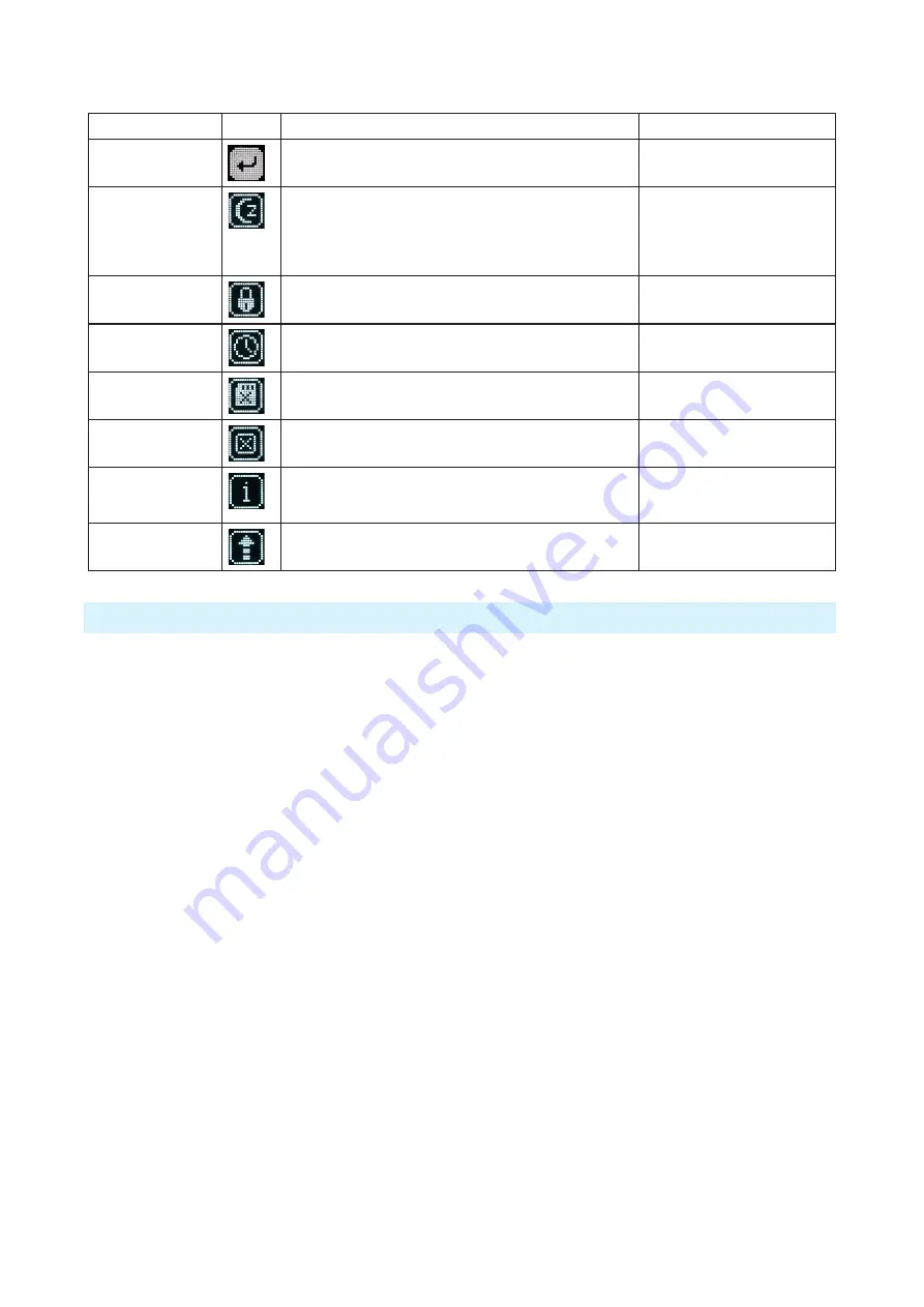
Selections

Icon

Description 

Options 

Exit

Returns to the main menu. 

Sleep 

When selected, the A10-TX goes into low-power Sleep 

mode. The blue LED flashes when the unit is in a sleep state. 

The unit returns to normal power operation when any button 

is pressed or the transmitter is activated from the A10-TX 

Remote App. 

• Sleep 

Lock Menu 

Activates a button lock to prevent unintentional changes to 

menu selections. 

• Unlock 

• Lock 

Set Time / Date 

Sets the time and date of the realtime clock. This value is 

applied to any recorded files. 

Format Card 

Deletes all files and data present on the inserted microSD 

card and prepares it for new recordings. 

OK - begins formatting process. 

Restore 

The restore function allows the user to reset the A10-TX to 

the factory default settings. 

Info 

Shows numerous attributes of the transmitter. 

• Serial Number 

• Firmware Revision 

• Frequency Band 

Update (Firmware) 

Updates the firmware of the transmitter using a firmware 

.PRG file on the microSD card. 

Basic Operation 

Frequency Selection 

The A10 Digital Wireless System operates in the UHF frequency band from 470 to 694 MHz. 

There are three models (two in some geographic markets) of the A10-TX transmitter to cover 

this frequency range. 
Multiple A10 Digital Wireless systems can be used simultaneously on nearby adjacent 

frequencies without worry of intermodulation interference since the A10 Digital Wireless System 

and its digital RF transmission is inherently immune to intermodulation. Systems can be used 

together when separated by at least 400 kHz. Use the scan tool on the A10-RX receiver to search 

for available frequencies. 


ª

When using A10 Digital Wireless systems in conjunction with analogue RF systems, an 

intermodulation plan needs to be addressed for analogue receivers. 

Channel, Sub Channel, Tune 

To simplify frequency selection, frequencies are divided into channels and sub channels. 

Frequencies corresponding to channels and sub channels depend on the TV Channel Mapping 

selected in the Systems menu. Three options are available, 6, 7, and 8 MHz spacing, X, Y, and Z 

respectively. These three settings generally correspond to three main geographic regions, USA, 

Australia/New Zealand, and Europe, respectively. 

•  Channel

 - corresponds to broadcast television channels used in geographic regions. 

Depending on the selected channel mapping, channels cover 6, 7, or 8 MHz. 

•  Sub Channel

 - channels are divided in 400 kHz increments called sub channels to speed up 

frequency selection. The number of sub channels depends on the channel mapping selected. 

Summary of Contents for A10-TX-US

Page 1: ...A10 TX Digital Transmitter User Guide ...

Page 2: ...Wiring Diagram 22 Battery Runtime Chart 22 Warranty 22 Certifications 23 Industry Canada Conformity 23 FCC Conformity 23 Declaration of Conformity 23 Minimize RF Exposure 23 Frequency Tables 24 X Frequencies 6 MHz Per TV Channel 24 Y Frequencies 7 MHz Per TV Channel 25 Z Frequencies 8 MHz Per TV Channel 26 Channel Assignments by Region 26 Copyright Doc Rev History Info Model A10 TX See separate do...

Page 3: ...imentation and customer experience The result is a wireless link with full 20 kHz audio bandwidth high dynamic range ultra low distortion an extremely low 2 millisecond end to end delay in Standard modulation The A10 System allows the user to operate up to 20 channels in an 8 MHz TV channel maximizing spectrum efficiency With firmware version 5 00 the A10 A20 Wireless System delivers the longest t...

Page 4: ...evel are set based on the input type At the Transmitter 1 Attach the straight antenna to the A10 TX 2 Attach an audio source to the 3 pin LEMO input connector 3 Insert AA batteries into the A10 TX battery compartment and power on the unit with the red On Off button 4 Set the audio input type to set to match the connected input 5 Set the transmitting frequency on the A10 TX match the frequency set ...

Page 5: ... hold to mute unmute 5 Power Button Press to power on the unit Press and hold to power down the unit Press and hold while holding Right button to lock unlock the unit 6 Audio Input Connector Balanced LEMO 3 connector Accepts mul tiple audio input types including unbalanced lavalier balanced microphone balanced line Also used for timecode input and output 7 Input Overload LED Red LED illuminates wh...

Page 6: ...ows the following Battery Condition Input Gain RF Output Power Frequency in MHz Frequency as Channel Sub Channel Input Level Meter Record Indicator RF Output Power three power levels are indicated Low 10 mW Medium 20 mW High 50 mW Input Gain gain applied to the input source in dB Battery Condition shows the battery voltage level of the transmitter batteries five segments Frequency in MHz the trans...

Page 7: ...equency increments in 25 kHz steps Audio Gain Controls the gain range of the audio input Gain range is input type dependent Gain control is in 1 dB increments Lavalier 0 dB to 40 dB Line setting 10 to 16 dB Mic setting 16 to 40 dB w 20dB pad Mic setting 36 to 60 dB Audio Setup Enters the Audio Setup sub menu Low Cut Limiter Lav Mic Line Mute Button Record TC Enters the Record TC sub menu Record St...

Page 8: ... enter Record mode This begins recording The Record status is remembered across sleep and power cycles Record displayed while Stopped Stop displayed while Recording File Info Shows important information about the file being recorded Time Elapsed Time Remaining Timecode File Name TX Record Mode Select the operational mode of the A10 TX TX Rec simultaneous wireless transmission and recording Rec Onl...

Page 9: ...t the battery type from the available options Alkaline NiMH Lithium User Groups Sets whether transmitter utilizes user groups User or manual frequency selection Factory User Use Load New Factory TV Ch Map Selects the TV channel spacing in MHz to ensure channel selection cooresponds to a specific geographic region See frequency chart X 6 MHz Y 7 MHz Z 8 MHz Display Enters the Display sub menu Brigh...

Page 10: ... markets of the A10 TX transmitter to cover this frequency range Multiple A10 Digital Wireless systems can be used simultaneously on nearby adjacent frequencies without worry of intermodulation interference since the A10 Digital Wireless System and its digital RF transmission is inherently immune to intermodulation Systems can be used together when separated by at least 400 kHz Use the scan tool o...

Page 11: ... V phantom power is available for balanced microphones The Selection Menu offers options for input type limiters and low cut filter Lavalier Microphones Unbalanced lavalier microphones wired in two wire mode are directly compatible with the A10 TX input When connected the A10 TX auto detects the presence of a lavalier microphone Balanced Microphones with Phantom Balanced microphones including phan...

Page 12: ... files See SD Utility File Conversion for more details After conversion a usable 48 kHz digital audio WAV file is made Files recorded in the A10 TX are approximately 1 3 the size of WAV files generated from corresponding MIC files saving valuable space on the microSD card Files have a maximum duration of six hours After six hours the file is automatically split into another recording Resulting WAV...

Page 13: ...nutes Use the Left and Right buttons to change the values 3 Press the centre Menu button to select the Return arrow and view current values Press again to exit External LTC Jamming External LTC timecode can be applied to the A10 TX to synchronize its internal timecode clock Synchronization of timecode clocks is called jam syncing To jam the A10 TX timecode clock navigate to Menu Record TC Timecode...

Page 14: ...strength Record status Mute Status ª Touch the Circle I icon to send identification signal to the transmitter 4 Turn Sleep mode On Off 5 Mute Unmute the transmitter 6 Start Stop recording at the transmitter 7 Adjust Gain 8 Set the low cut filter 9 Adjust RF Power 10 Change TV Ch Sub Ch and Frequency ª When a user group is loaded the TV Ch Sub Ch Frequency section changes to User displaying the use...

Page 15: ... new file 3 Name the new group 4 Select a range of frequencies via the Band drop down list Options include A B C D and Any This will automatically restrict users in the group to the frequencies within that band Selecting Any will make frequencies within all bands available for assignment to users in the group ª All A10 TX will have the available bands listed on the printed label inside the battery...

Page 16: ... 1 In SD Utility select a User Group in the drop down list 2 Select Remove Group Loading User Groups onto A10 Transmitters A user group is transferred to the A10 TX via the microSD card inserted into the transmitter ª For instructions on sending a user group to A10 receivers see the A10 RX User Guide To load a user group on an A10 TX 1 If the microSD card has not been formatted by the transmitter ...

Page 17: ...eive firmware update notifications Firmware is installed on the A10 TX using the A10 TX menu Download the latest firmware PRG from the Sound Devices website at https www sounddevices com download A Change List of new features for the latest firmware can also be found on this webpage To update firmware 1 Download the new firmware PRG update file from the Sound Devices website and copy the file onto...

Page 18: ... timecode values conformed to a CSV Sound Report exported as WAV and more SD Utility is also a companion application for the Audio Ltd A10 RX and the Sound Devices A20 Mini For details specific to those products please refer to their respective user guides Installing SD Utility 1 Download the SD Utility Installer for MacOS or Windows from https www sounddevices com download prod sd utility 2 Open ...

Page 19: ...dow then navigate File Remove Highlight the file s to be removed from the Source window then press the Delete key Organizing Source Files Click on a Information Header cell to order the list of files in the Source Window by information For example click the Start TC cell to arrange the files by timecode start times from lowest to highest Click again to reverse the order from highest to lowest To m...

Page 20: ...g Pre and Post Roll to conformed files can benefit post production with access to audio just prior to and following head and tail slates To add pre and post roll to conformed WAV files select the Pre Post Roll check box and enter a value from 0 to 10 seconds in 1 second steps If the source file does not contain audio data for the duration of the pre or post roll location the exported file will beg...

Page 21: ...tting 0 dB to 40 dB 1 dB increments Line setting 10 to 16 dB 1 dB increments Mic setting w 20 dB pad 16 to 40 dB 1 dB increments Mic setting w no pad 36 to 60 dB 1 dB increments Input Gain Input Type Input Impedance ohms Input Clipping Level minimum gain Lavalier 6 8k 6 dBu Bal Mic plus P48 and P12 2 5k 10 dBu 20 dB pad Bal Line 3k 24 dBu Low Frequency Cut Off 40 Hz 60 Hz 80 Hz 100 Hz 200 Hz user ...

Page 22: ...wer High 4 hr 33 min 2 hr 21 min 7 hr 57 min recording only 48 V 9 hr 47 min 6 hr 2 min 17 hr 44 min 50 mW 48 V 3 hr 29 min 1 hr 33 min 6 hr 20 min ª The 48 V tests were run with a Schoeps CMIT Mini Other settings used for tests to compile the chart are Low Cut Off Limiter On 40 dB gain for 48 V 30 dB gain for Lavalier freshly formatted 8G card 16 hr record time Bluetooth On Blue LED On and Bright...

Page 23: ...including interference that may cause undesired operation Changes or modification not expressly approved A10 TX frequency ranges supplied for use in USA 470 2 547 8 MHz 518 2 607 4 MHz ª Frequency range 608 614 MHz is forbidden for use in US ª Warning Any modifications or changes made to this device unless explicitly approved by Audio Ltd may invalidate the authorisation of this device Operation o...

Page 24: ...4 559 8 29 560 2 560 6 561 561 4 561 8 562 2 562 6 563 563 4 563 8 564 2 564 6 565 565 4 565 8 30 566 2 566 6 567 567 4 567 8 568 2 568 6 569 569 4 569 8 570 2 570 6 571 571 4 571 8 31 572 2 572 6 573 573 4 573 8 574 2 574 6 575 575 4 575 8 576 2 576 6 577 577 4 577 8 32 578 2 578 6 579 579 4 579 8 580 2 580 6 581 581 4 581 8 582 2 582 6 583 583 4 583 8 33 584 2 584 6 585 585 4 585 8 586 2 586 6 5...

Page 25: ... 1 579 5 579 9 580 3 580 7 581 1 581 5 581 9 582 3 582 7 36 583 3 583 7 584 1 584 5 584 9 585 3 585 7 586 1 586 5 586 9 587 3 587 7 588 1 588 5 588 9 589 3 589 7 37 590 3 590 7 591 1 591 5 591 9 592 3 592 7 593 1 593 5 593 9 594 3 594 7 595 1 595 5 595 9 596 3 596 7 38 597 3 597 7 598 1 598 5 598 9 599 3 599 7 600 1 600 5 600 9 601 3 601 7 602 1 602 5 602 9 603 3 603 7 39 604 3 604 7 605 1 605 5 6...

Page 26: ...4 577 8 578 2 578 6 579 0 579 4 579 8 580 2 580 6 581 0 581 4 581 8 35 582 2 582 6 583 0 583 4 583 8 584 2 584 6 585 0 585 4 585 8 586 2 586 6 587 0 587 4 587 8 588 2 588 6 589 0 589 4 589 8 36 590 2 590 6 591 0 591 4 591 8 592 2 592 6 593 0 593 4 593 8 594 2 594 6 595 0 595 4 595 8 596 2 596 6 597 0 597 4 597 8 37 598 2 598 6 599 0 599 4 599 8 600 2 600 6 601 0 601 4 601 8 602 2 602 6 603 0 603 4...

Page 27: ...Post Office Box 576 E7556 State Rd 23 and 33 Reedsburg Wisconsin 53959 USA support sounddevices com 1 608 524 0625 main 800 505 0625 toll free U S only www sounddevices com ...

Reviews: