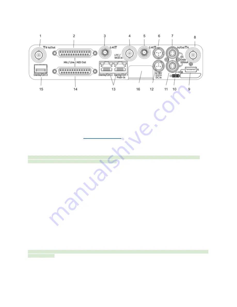
Rear Panel
1 & 8: Antenna Connector A & B Inputs / Cascade Outs
●
BNC connectors for connecting active, passive, or smart antennas.
●
Cascade outs for looping through the front panel antenna A & B inputs. Only available when front panel antennas are
selected in the (
Main Menu>RF
) menu. The cascade out passively splits the incoming signal, resulting in approximately
3.5 dB of loss. In some situations, additional antenna gain and/or amplification may be desirable to maintain excellent
range.
2 & 14: Top & Bottom D-Sub Audio Output Connectors
25-pin D-Sub connectors for outputting analog (mic/line level) or AES digital. See menu (
Main Menu>Audio Output).
Disabled when
mounted to an 8-Series via the expansion port. Note: the pin-out follows the AES59 standard. The analog output pin-out is different
from the AES digital output pin-out. See
section for more information.
3 & 5: 2.4 GHz Antenna Connectors
Dual SMA-F ports for connecting 2.4 GHz SMA-M antennas for NexLink. Both antennas need to be connected.
Important:
Only use the 2.4 GHz SMA-M antennas supplied with the A20-Nexus or equivalent. Do not use 2.4 GHz RP-SMA
antennas such as those used for the 8-Series bluetooth antenna.
4: LTC / Wordclock Input
BNC for connecting LTC or Wordclock input. Nexus auto-detects whether the signal is LTC or Wordclock including the associated
frame rate or sample rate. Disabled when mounted to an 8-Series via the expansion port.
6 & 12: DC Inputs
Dual TA4-M, 10-18V DC inputs. Highest voltage takes precedence. Disabled when docked to an 8-Series via the expansion port.
7 & 11: DC Outputs
Dual, 4-pin Hirose female DC outputs (500 mA max between both outputs) for powering IFB transmitters, camera hops, and other
low power peripherals. Disabled when docked to an 8-Series via the expansion port.
When powered via TA4, voltage is passed through from the DC input (10-18V). When powered via PoE+, DC Outputs supply 12V
DC.
9: USB-A Port
Multi-function USB-A port for:
●
Pairing and syncing timecode to A20 transmitters. Connect the transmitter to Nexus using a USB-C to USB-A cable.
●
Connecting a USB keyboard for naming channels, quick setup files and network. The USB keyboard is active whenever
the virtual keyboard screen is displayed.
●
Mounting a USB thumb drive for updating firmware and loading/saving settings.
Tip:
The USB-A port supports USB hubs so that multiple devices can be connected at the same time. Maximum power output of 2.5
Watts (5V, 500 mA)
10: USB-C Port
For factory use only.
A20-Nexus
User Guide
9


