

4
Spectralizer
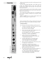
SPL digital audio processors are designed in cooperation with
Spectral Design of Bremen, Germany, who are responsible for
the DSP programming.
C
oncept:
The S
PECTRALIZER
is the first digital harmonics processor
employing a new process which allows you to re-synthesize
second and third harmonics separately, and with full control
over their amplitude.
The S
PECTRALIZER
benefits from SPL's expertise in psycho-acou-
stic principles and is the ideal tool to improve the clarity, trans-
parency and intelligibility of any signal in the digital domain.
A single instrument or vocal gains better penetration within a
mix, while complete mixes benefit from improved subjective
loudness without a measurable change in levels.
While developing the DSP-program, a strong emphasis was
placed on achieving warm and smooth sounding harmonic re-
synthesis. The digital domain tends to be susceptible to “sharp-
ness” at the HF end of the spectrum, which made the design of
the S
PECTRALIZER
all the more demanding. The result is a tool able
to increase brightness and detail without adding harshness or
sounding fatiguing.
In comparison to ostensibly similar analogue systems, the
S
PECTRALIZER
does not produce any phase deterioration, nor
introduce unmusical intermodulation products.
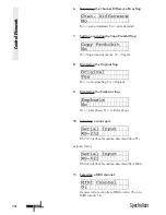
O
peration:
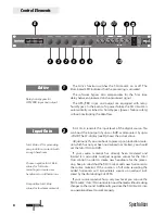
The S
PECTRALIZER
is fitted with six encoder controls,
and the actual parameters values are shown in the LCD
window. I
NPUT
G
AIN
sets the overall input level with gain adjust-
ment available from -20 dB to +6 dB, while the starting
frequency for the re-synthesis of the harmonics is set using the
F
REQUENCY
control. This functions as a high-pass filter adjustable
over the range 1kHz to 7 kHz in 500 Hz steps; signals with a
frequency lower than that selected using the F
REQUENCY
control
remain unaffected. The D
ENSITY
control offers a choice of six
settings to determine the amplitude envelope of the added
harmonics and works rather like a digital compressor to
increase the density of the re-synthesized harmonics – which
makes them more prominent. The 2
ND
and 3
RD
H
ARMONIC
controls set the relative levels of the re-synthesized harmonics
while the M
IX
control defines the balance between the new
harmonics and the original signal.
The S
PECTRALIZER
has three switch functions: S
OLO
mutes the
original input signal so that the added harmonics can be heard
in isolation while K
ICK
adds a greater proportion of harmonics
to transients (attack parts of the signal).
The A
CTIVE
button switches the S
PECTRALIZER
in and out of
operation; when connected via AES/EBU, a relay-operated
hard bypass switches the digital input directly to the output.
Signal flow remains uninterrupted, even if the mains power is
switched off.
The software bypass function compensates for the inevitable
(but very short!), digital domain processing delay so as to avoid
Introduction
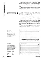
Re-synthesizing second and
third harmonics separately
Improving clarity, intelligibi-
lity and depth without
introducing harshness
Warm and smooth sounding
harmonic re-synthesis
Easy and intuitive
operation


