background image

8

Spectralizer

3

2

7

6

5

4

12

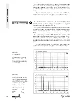
Relay hard-bypass for
AES/EBU input and output

I

NPUT

G

AIN

= 0 for processing

pre-production material with
enough headroom

Choose negative I

NPUT

G

AIN

values for full scale 
recordings to create new
headroom to add harmonics

Use positive I

NPUT

G

AIN

values for low level material

Control Elements

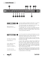
The A

CTIVE

function switches the S

PECTRALIZER

on or off. The

illuminated LED indicates that the processing is activated. 

The software bypass also compensates for the 5 ms time

delay between processed and unprocessed signal.

The AES/EBU input and output are equipped with relay-

hard-bypass. In the event of a power failure the S

PECTRALIZER

is

automatically switched to hard-bypass (power failure safety)
without interrupting the data flow.

I

NPUT

G

AIN

controls the input level of the digital source. You

can boost the input gain by up to +6 dB or attenuate it by up to
-20 dB. The LC-display (see 8) shows the actual value.

Adjustment:

If you are about to process pre-production mate-

rial which has not yet been normalized nor limited, you should
set the I

NPUT

G

AIN

to 0 dB. 

If your source material has already been mastered and

limited it is advisable to adjust negative values for the I

NPUT

G

AIN

control in order to create new headroom for the proces-

sing. Keep in mind that the S

PECTRALIZER

adds new harmonics to

the source material. If the source is a full scale recording the
added harmonics will immediately create an overload indi-
cated by the illuminating C

LIP

LEDs.

If your source material has a very low level you can use the

S

PECTRALIZER

´

S

I

NPUT

G

AIN

control to boost the level without making

changes to the sound. Additionally you drive the S

PECTRALIZER

into

an operational level to work properly. 

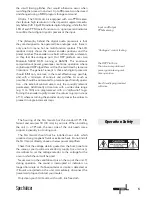
Active

2

1

1 13

9 10

8

Input Gain

11

Summary of Contents for Spectralizer 9631

Page 1: ...Manual Digital Harmonics Processor Spectralizer Model 9631 ...

Page 2: ...ion of SPL Limitations of Liability In no event will SPL be liable for any damages including loss of data lost profits cost of cover or other special incidental consequential or indirect damages arising from the use of the unit however caused and on any theory of liabi lity This limitation will apply even if SPL or an authorized dealer has been advised of the possibility of such damage SPL electro...

Page 3: ... I would like to start with my thanks to all our staff who created what is to be described here Special thanks go to Jörg Houpert Klaus Peter Webersinke and Andreas Skäbe from Spectral Design as well as Harald Obenland from Octum elec tronics The importance of their exceptional qualification and talents cannot be overestimated Our products are often tested and compared in many publica tions and by...

Page 4: ...s the overall input level with gain adjust ment available from 20dB to 6dB while the starting frequency for the re synthesis of the harmonics is set using the FREQUENCY control This functions as a high pass filter adjustable over the range 1kHz to 7kHz in 500Hz steps signals with a frequency lower than that selected using the FREQUENCY control remain unaffected The DENSITY control offers a choice ...

Page 5: ...friendly opera tion the external controls access only the sonically relevant parameters Additionally all controls with a wide value range e g 0 to 100 are programmed with an alpha dial logic Turning the encoder rapidly causes the values to jump in steps of 10 whereas turning the encoder slowly causes the values to proceed in single increment steps The housing of the SPECTRALIZER has the standard 1...

Page 6: ...t your computer with the SPECTRALIZER via a serial port with a standard Z modem cable RS 232 for PC and RS 422 for MAC 2 Open a terminal program like Hyperterminal on PC and make the following adjustments Baud rate 9600 Stop bit 1 Parity none Data bit 8 Handshake no Transfer mode ZMODEM 3 Switch on the SPECTRALIZER and depress both PRESET UP and PRESET DOWN until the LC display says wait for Zmode...

Page 7: ...s 2 Set MIX to 50 You will notice an increase in high frequencies above 1kHz starting position FREQUENCY 3 Set DENSITY to 1 to increase the audibility of the harmonics in the next step 4 Set 2ND HARMONIC to 50 and 3RD HARMONIC to 30 5 If you are using full scale material for this initial test drive the CLIP LEDs may illuminate Reduce the INPUT GAIN to give additional headroom for the new harmonics...

Page 8: ...rols the input level of the digital source You can boost the input gain by up to 6dB or attenuate it by up to 20dB The LC display see 8 shows the actual value Adjustment If you are about to process pre production mate rial which has not yet been normalized nor limited you should set the INPUT GAIN to 0dB If your source material has already been mastered and limited it is advisable to adjust negati...

Page 9: ...EQUENCY control Until now you have not yet added any harmonics The increase in high frequencies is a boost of all frequencies above 1kHz You can change the starting frequency by turning the FREQUENCY encoder clockwise to higher frequen cies For some applications this may already do the job To add harmonics set 2ND HARMONIC to 50 and 3RD HARMONIC to 30 If the audible effect is very subtle increase ...

Page 10: ...audible use the DENSITY control see DENSITY 7 to increase their loudness The 3RD HARMONIC encoder controls the intensity of the added third harmonics which are being generated above the adjusted highpass frequency see FREQUENCY 3 The third harmonics are odd harmonics which carry brilliance but also sharpness and aggressiveness A good combination of even and odd harmonics is the key to a natural so...

Page 11: ...ng and harmonics generation The KICK function boosts the amplitude of the generated harmonics in the event of creation attack period After that the amplitude drops back to its original value KICK should be used when you want to apply additional sparkle and presence to the signal The SPECTRALIZER allows you to store up to 99 presets which can be changed by MIDI program change command If you want to...

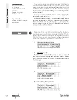
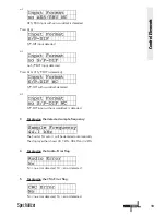
Page 12: ... to activate the UP and DOWN buttons Depressing STORE and APPLY simultanouesly for about one second gets you into a hardware dialogue called INFO The LC display shows status informations of the digital data stream With UP DOWN you will jump from one page to the next or previous If a selection is provided use APPLY to select 1 Software version and date 2 Selecting inputs The SPECTRALIZER automatica...

Page 13: ...cted S P DIF with wordclock detected or S P DIF input without wordclock is detected 3 Displaying the detected sample frequency The SAMPLE FREQUENCY will be detected automatically The display either shows 44 1 kHz 48 kHz or 32 kHz 4 Displaying the Audio Error flag NO no error detected YES error detected 5 Displaying the CRC Error flag NO no error detected YES error detected ...

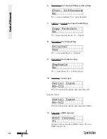
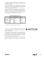
Page 14: ...lag set 8 Displaying the Original flag NO no Original flag YES Original 9 Displaying the Emphasis flag NO no emphasis YES with emphasis 10 Selecting a serial port RS 232 interface for update download from PCs or press APPLY RS 422 interface for update download from MACs 11 Selecting a MIDI channel Depress APPLY to step from MIDI CHANNEL 01 up to MIDI CHANNEL 16 Control Elements ...

Page 15: ...lly be useful when you are mastering a song for example that requires different settings for chorus refrain or bridge The APPLY LED illuminates indica ting that a program change command is received You leave the INFO pages by depressing STORE The OUTPUT LED chains are PPM peak level meters with signal and clip indicators The metering offers 1dB resoltion for the last 3dB before 0dB The first LED i...

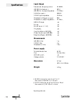
Page 16: ...splay yes Input transformer AES EBU yes Output transformer AES EBU yes Relay Hard Bypass AES EBU yes Measurements AES EBU Jitter 1ns S P DIF Jitter 3ns Wordclock In Jitter 1 5ns Power supply Torroidal transformer 60 VA Fuse 1A slow blow GND Lift switch yes Voltage selector 115V 230V Dimensions 19 1U 482 x 44 x 350mm Weight 4 9 kg 1 AES EBU is defined for levels from 2V to 7V Measurements AES EBU 4...

Page 17: ...thorized SPL warranty repair facility in the country where purchased or to the SPL factory in Germany in the original packaging or a replacement supplied by SPL with all trans portation costs and full insurance paid each way by the purchaser or owner All remedies and the measure of damages are limited to the above services It is possible that economic loss or injury to person or property may resul...

Reviews: