5
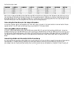
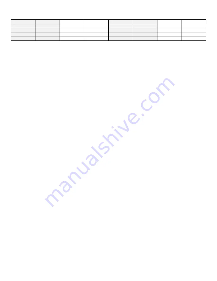
for the channel you need.
CHANNEL
SWITCH CHANNEL
SWITCH CHANNEL
SWITCH CHANNEL
SWITCH
1
0000 5
0100 9
0100 13
1100
2
0001 6
0101 10
0101 14
1101
3
0010 7
0110 11
0110 15
1110
4
0011 8
0111 12
0111 16
1111
After you have selected the MIDI channel slide the board back inside the case taking care that the board slides all the way in (you
may need to push the bottom of the plastic bezel on the rear panel downward a slight amount while pushing the board in so the
board goes all the way in). When the board is all the way in, attach the screws and lightly tighten the screw only enough to make
contact with the panel. Do not overtighten the screw to avoid scratching the panel.
Connecting the PowerSwap to the Amp and Speakers
Connect the “speaker” jack of the amplifier to the “COM” jack using a standard ¼” instrument cable and connect each of the two
speakers to the “A” and “B” jacks on the PowerSwap using standard ¼” instrument cables.
Connecting MIDI to the PowerSwap
Connect a standard MIDI cable between your MIDI foot controller MIDI OUT jack and the PowerSwap MIDI IN jack. Connect an
additional cable between the MIDI THRU jack on the PowerSwap and the MIDI IN jack of the next MIDI device in your chain as you
normally would. The PowerSwap does not interfere with the MIDI signal and simply passes through all data seen on the MIDI IN
jack directly to the MIDI THRU jack. Power must be applied to the PowerSwap in order for MIDI data to pass through to the next
device.
Connecting a Mechanical Footswitch to the PowerSwap
You may control the PowerSwap without MIDI by connecting either a push on/push off or a momentary mechanical footswitch to
the MIDI IN port. In order for the unit to determine which style switch you are using a switch inside the unit must be set
accordingly. Since most mechanical footswitches for musical instrument use are connected to a standard 1/4” jack, the jack will


