www.soundskulptor.com
Document revision 2.1 – Last modification : 11/09/20
DI board Assembly guide
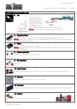
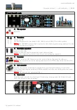
4. Film capacitor
Add C22.
5. Transistors
Add Q1 and Q2.
The PCB has provision for two pinouts for Q2. With the current 2SK170, use the A position.
Warning
: Q1 (2N7000) is a device that is sensitive to static electricity before being soldered. It is safer
to handle it without your shoes on.
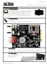
6. Electrolytic capacitors
Add C23, C24, C25.
Solder one lead first, adjust verticality then solder the second lead.
Warning
: The +lead must go into the +hole. Do not reverse (they may explode !)
7. Connector
Solder the connector CN3. Solder one pin first, check verticality, then solder the other pins.
Warning
: the connector pins must be exactly perpendicular to the PCB to allow proper insertion in the
preamp board.
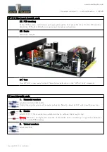
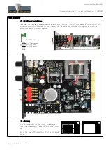
8. Jack connector
Add CN1. The position of the socket is important for a good front-plate matching. It must sit flat
on the PCB. Press firmly the socket on the PCB and solder one of the pins. Check position then solder
the other pins.
Warning
: the hole must face outside the PCB ;-)
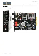
9. Visual check
Brush the solder side with a hard tooth brush to remove any remaining solder bits. Make a full visual
check. The DI board is ready for testing !
Copyright ©2013 SoundSkulptor


