www.soundskulptor.com
Document revision 1.3 – Last modification : 28/02/20
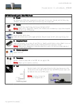
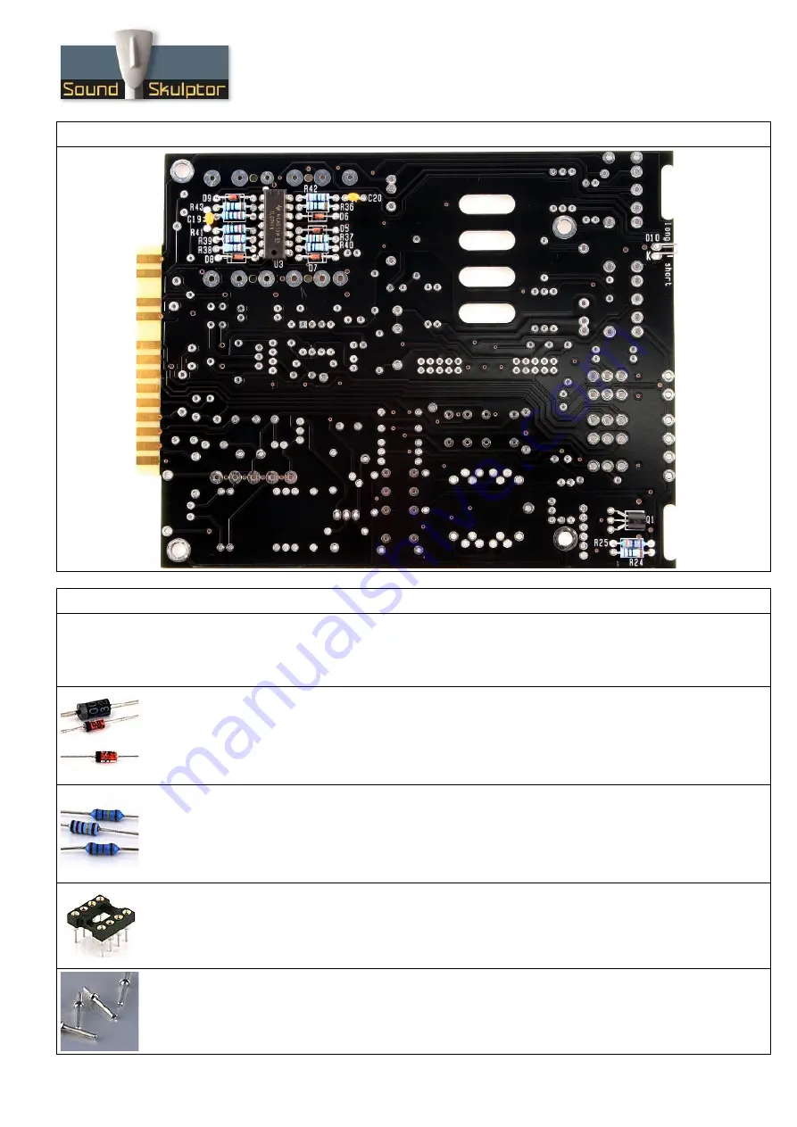
MP 566 Assembly guide – Main PCB, B side
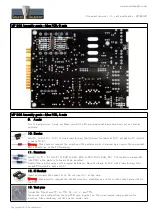
MP 566 Assembly guide – Main PCB, A side
9. A side
Turn the board over, A side up. Make sure all the B side component leads have been cut as short as
possible.
10. Diodes
Add D1 to D4, D11 to D14. Use a lead forming tool to bend the leads at 0.4”, except for D14 which
is bent at 0.6”.
Warning
: Make sure to respect the direction of the diodes which is marked by a ring on the component
and a double line on the PCB marking.
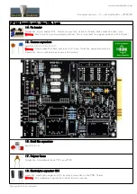
11. Resistors
Add R1 to R11, R13 to R18, R20 to R23, R26 to R35, R45, R46, R51. The resistors marked NC
(like R33) in the parts-list should not be installed.
Control the resistor values with a digital multimeter. Bend the leads at 0.4” with a lead forming tool
except R34 which is bent at 0.6”.
12. IC Socket
Insert and solder the socket of UI. Do not insert U1 at this time.
Warning
: Make sure to respect the socket direction, identified by a notch on the socket and a dot on
the PCB.
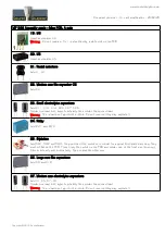
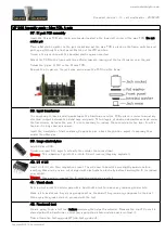
13. Test pins
Solder the 8 test pins TP1 to TP4, 0V, V+, V- and TP8.
These pins are inserted from the top PCB side, long tail up. They may require some pressure for
insertion. After soldering, cut flush on the solder side.
Copyright ©2015 SoundSkulptor


