www.soundskulptor.com
Document revision 1.3 – Last modification : 28/02/20
MP 566 Assembly guide – Main PCB, A side
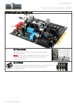
37. DI jack PCB assembly
Insert the DI jack PCB into the 6 pins header located in the lower left corner of the main PCB. Do not
solder yet.
Place a flat plastic washer on the jack socket and put the main PCB in place on the frame, switches and
pots going through the front panel. Watch out the LED position.
Screw in the jack nose with the bevelled plastic spacer inserted.
Attach the PCB to the frame with three 25mm spacers, leaving out the fourth spacer near the jack.
Solder the 6 pins of CN1on the DI Jack PCB.
Remove the 3 spacers, the jack nose and remove the PCB from the frame.
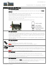
38. Input transformer
It is necessary to leave a small gap between the transformer and the PCB surface in order to avoid any
electrical contact between the metal case and pads. Fit two layers of double sided adhesive tape, under
the transformer, between the pins. It is not necessary to remove the second protective layer from the
tape as it is only used as a spacer.
Insert the transformer. Start soldering 2 opposite pins, check the position, adjust if necessary then
solder the other pins.
39. Large electrolytics
Add C22 and C23.
Solder one lead first, adjust verticality then solder the second lead.
Warning
: The +lead must go into the +hole. Do not reverse (they may explode !)
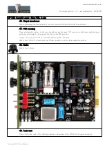
40. U1 & U4
Insert U1 & U4 into their respective socket. You will need to bend the pins slightly inwards before
inserting. Make sure you are not charged with electrostatic electricity before handling the IC (or remove
your shoes).
Warning
: Make sure to respect the IC direction, marked by a notch.
41. Visual check
At this point, brush the solder side with a hard tooth brush to remove any remaining solder bits.
Make a full visual check. Any missing component on the board ? Any remaining component in the box ?
When everything looks correct, proceed with the test.
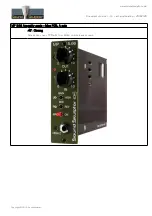
42. Functional test
We are going to do a first test before soldering the output transformer. Because the clip LED circuit is
placed below the transformer, correcting a possible mistake would be easier without it.
Please follow the testing guide MP566-test-guide.pdf.
Copyright ©2015 SoundSkulptor


