www.soundskulptor.com
Document revision 1.1 – Last modification : 10/08/17
SK25 Assembly guide
12. Q9 & Q10 assembly
Similarly, attach Q10 (BD140) to the heatsink PCB marked “SK25” with a
M3x12 mm screw and screw it into the other side of the spacer. The transistor
is placed on the side with no writing.
Tighten softly, by hand for now.
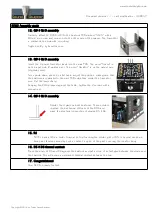
13. Q9 & Q10 assembly
Insert the 2 power transistor leads into the main PCB. The word “Sound” is
on the input side (2 golden pins). The word “Skulptor” is on the output side
(4 golden pins).
Turn upside down, press on a flat table, adjust the position, making sure that
the heatsinks are parallel to the main PCB edge then solder the transistor
pins. Cut the leads sharp.
Keeping the DOA pressed against the table, tighten the 2 screws with a
screwdriver.
14. Q9 & Q10 assembly
Solder the 4 pads on both heatsinks. These solders
improve the mechanical stiffness of the DOA and
make the electrical connection of diodes D5 & D6.
15. R1
Pull R1 back a little in order to avoid its top touching the solder joint of D5. In several cases we
have seen failures caused by such a contact in spite of the paint covering the resistor body.
16. D5 & D6 thermal contact
Press the body of D5 and D6 against the heatsink and put a drop of instant glue between the diode and
the heatsink. This will ensure a permanent thermal contact between the two.
17. Congratulations!
Your SK25 is ready for test.
Copyright ©2014 to Today SoundSkulptor


