
www.soundskulptor.com
Document revision 1.1 – Last modification : 10/08/17
SK99 Assembly guide
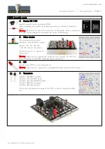
4. Diodes D5 & D6
Add D5 and D6 on the 2 heatsink PCB's.
When soldering, be careful not putting any solder on the power transistor
plane.
Warning
: Make sure to respect the direction of the diodes which is marked by
a ring on the component and a double line on the PCB marking.
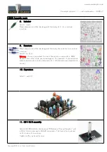
5. Other diodes
These diodes are mounted
vertically, cathode (black ring) up.
Add D1, D2, D7, D8, D9:
1N4148, blue on the picture.
Add D4: zener 5.1V, green on
the picture.
Warning
: Make sure to respect the direction of the diodes. D7, D8, D9
are mis-labeled on the PCB, follow the layout document.
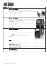
6. LED
Add the red LED D3, red on the picture.
Warning
: Make sure to respect the long lead/short lead direction of the diode.
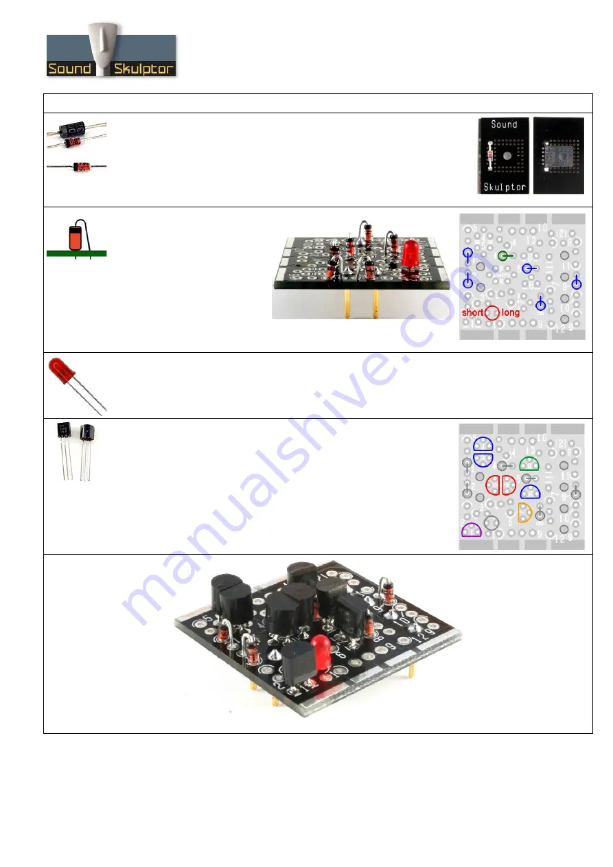
7. Transistors
Add Q1: BC560C (purple)
Add Q2, Q3: KSA992 (red)
Add Q4, Q5, Q6: BC550C (blue)
Add Q7: BC556C (orange)
Add Q8: BC546C (green)
Press firmly the transistors against the PCB in order to keep the profile
low.
Copyright ©2014 to Today SoundSkulptor


