
www.soundskulptor.com
Document revision 1.1 – Last modification : 10/08/17
SK99 Assembly guide
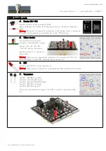
8. Inductor
Add L1 (red).
Bend sharply one of the leads against the body of L1 for a vertical
insertion.
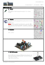
9. Resistors
Bend sharply one of the leads against the body the resistor for a vertical
insertion.
Add R1 to R13.
Warning
: It is very important to check the resistors value with a DMM
because the colour code can be ambiguous. For example 1K (brown-black-
black-brown-brown) can be confused with 110R (brown-brown-black-black-
brown).
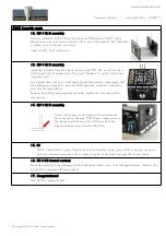
10. Capacitors
Add C1 and C2.
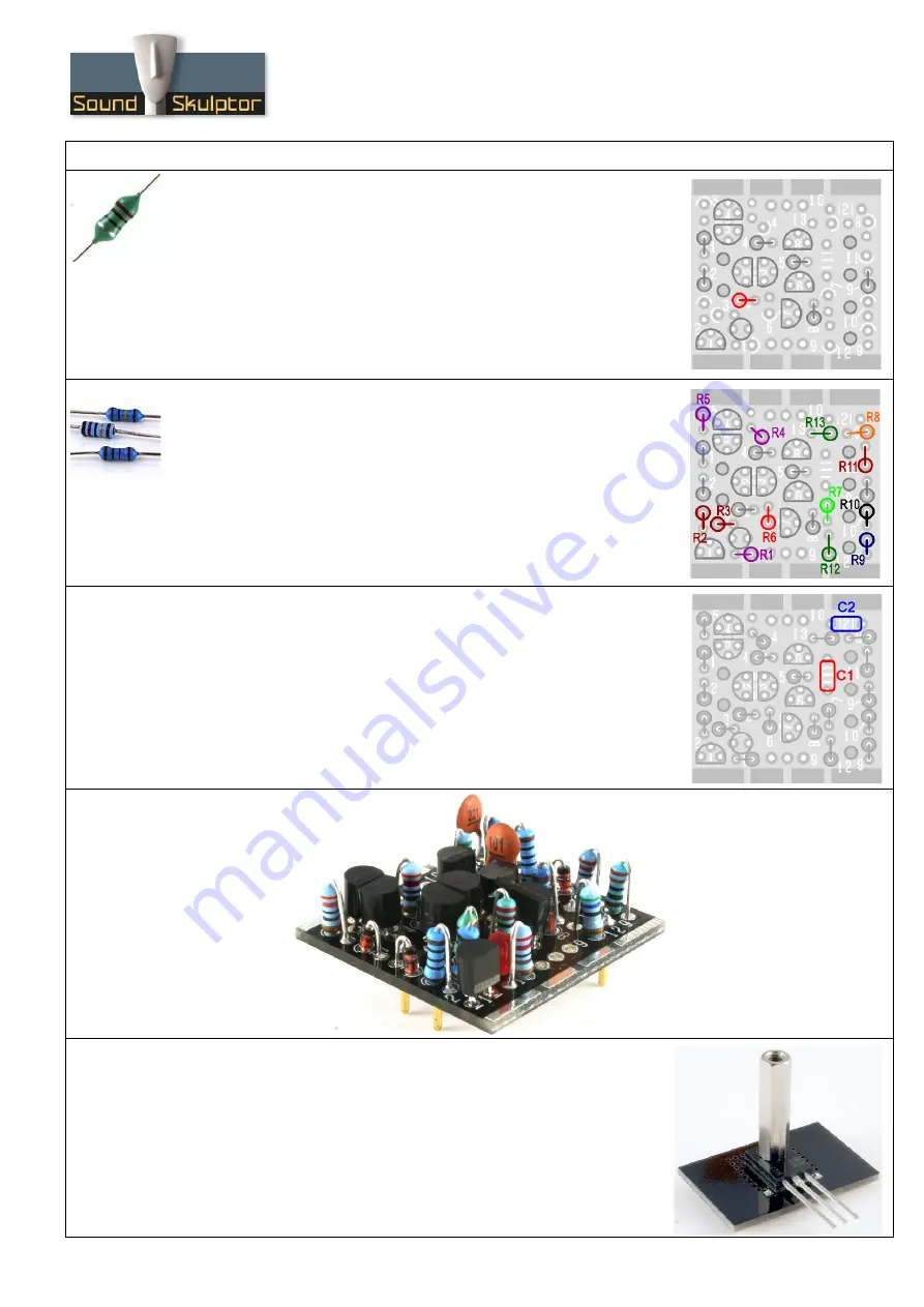
11. Q9 & Q10 assembly
Attach Q9 (BD139) to the heatsink PCB marked “Sound Skulptor” with
a M3x12 mm screw and a M3x20 mm spacer. The transistor is placed
on the side with no writing.
Tighten softly, by hand for now.
Copyright ©2014 to Today SoundSkulptor


