background image

www.soundskulptor.com

Document revision 1.1 – Last modification : 10/08/17

SK99 Assembly guide

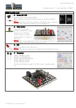
12. Q9 & Q10 assembly

Similarly, attach Q10 (BD140) to the heatsink PCB marked “SK99” with a 
M3x12 mm screw and screw it into the other side of the spacer. The transistor 
is placed on the side with no writing.

Tighten softly, by hand for now.

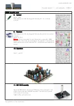
13. Q9 & Q10 assembly

Insert the 2 power transistor leads into the main PCB. The word “Sound” is 
on the input side (2 golden pins). The word “Skulptor” is on the output side 
(4 golden pins).
Turn upside down, press on a flat table, adjust the position, making sure that 
the heatsinks are parallel to the main PCB edge then solder the transistor 
pins. Cut the leads sharp.

Keeping the DOA pressed against the table, tighten the 2 screws with a 
screwdriver.

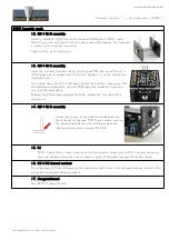
14. Q9 & Q10 assembly

Solder the 4 pads at the bottom of both heatsinks 
that connect to the main PCB. These solders improve 
the mechanical stiffness of the DOA and make the 
electrical connection of diodes D5 & D6.
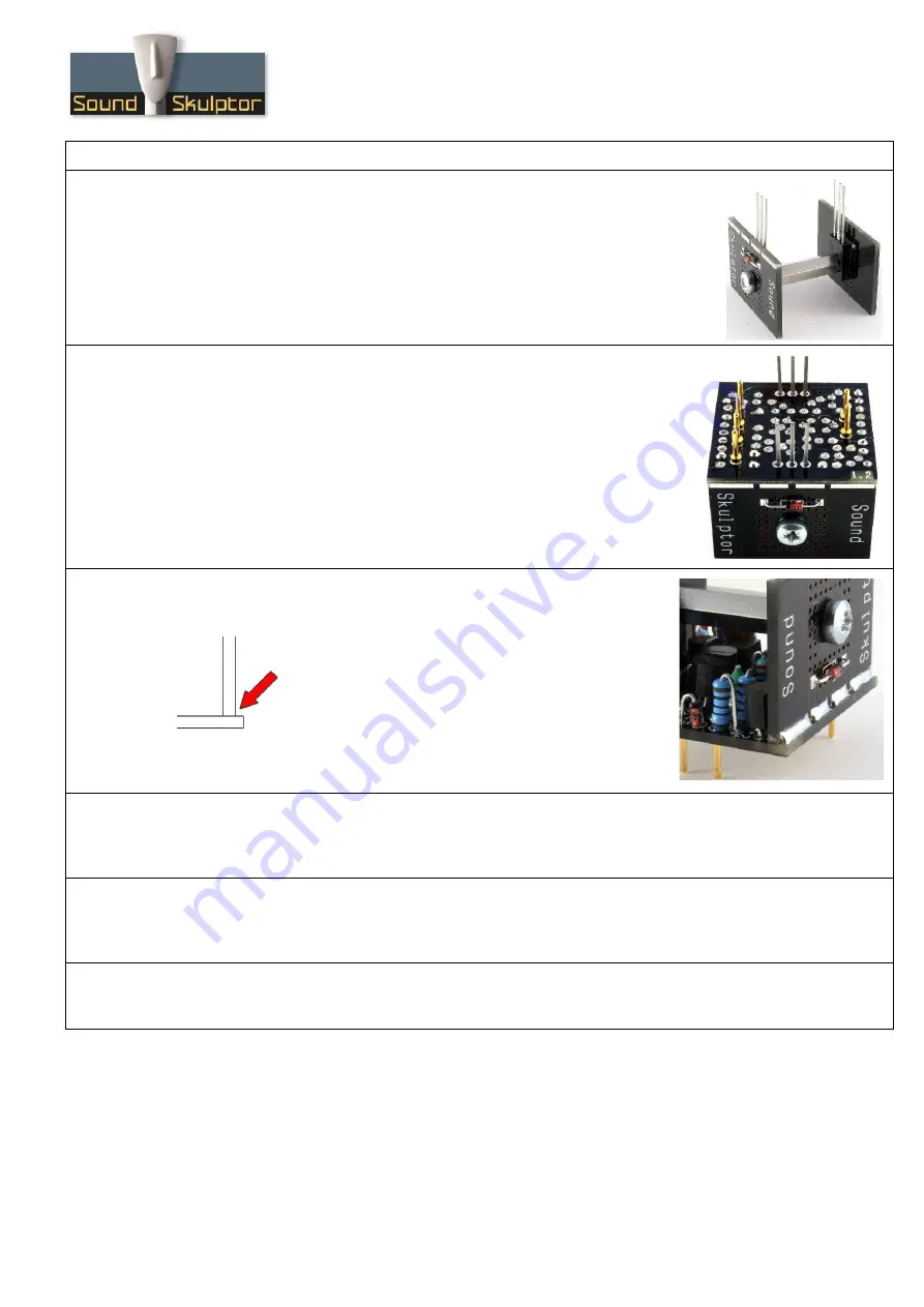
15. R1

Pull R1 back a little in order to avoid its top touching the solder joint of D5. In several cases we 
have seen failures caused by such a contact in spite of the paint covering the resistor body.

16. D5 & D6 thermal contact

Press the body of D5 and D6 against the heatsink and put a drop of instant glue between the two. This 
will create a permanent thermal contact.

17. Congratulations!

Your SK99 is ready for test.

Copyright ©2014 to Today SoundSkulptor

Summary of Contents for SK99

Page 1: ...e connection between the top and bottom pads is already done The parts must be soldered only from the bottom side unless differently stated Use only small diameter solder 0 5 or 0 7 mm 1mm maximum Use the minimum possible amount of solder Bad joints are almost always caused by too much solder Here are two excellent introduction to soldering videos http www eevblog com 2011 06 19 eevblog 180 solder...

Page 2: ...ed vertically cathode black ring up Add D1 D2 D7 D8 D9 1N4148 blue on the picture Add D4 zener 5 1V green on the picture Warning Make sure to respect the direction of the diodes D7 D8 D9 are mis labeled on the PCB follow the layout document 6 LED Add the red LED D3 red on the picture Warning Make sure to respect the long lead short lead direction of the diode 7 Transistors Add Q1 BC560C purple Add...

Page 3: ... R1 to R13 Warning It is very important to check the resistors value with a DMM because the colour code can be ambiguous For example 1K brown black black brown brown can be confused with 110R brown brown black black brown 10 Capacitors Add C1 and C2 11 Q9 Q10 assembly Attach Q9 BD139 to the heatsink PCB marked Sound Skulptor with a M3x12 mm screw and a M3x20 mm spacer The transistor is placed on t...

Page 4: ...he main PCB edge then solder the transistor pins Cut the leads sharp Keeping the DOA pressed against the table tighten the 2 screws with a screwdriver 14 Q9 Q10 assembly Solder the 4 pads at the bottom of both heatsinks that connect to the main PCB These solders improve the mechanical stiffness of the DOA and make the electrical connection of diodes D5 D6 15 R1 Pull R1 back a little in order to av...

Reviews: