www.soundskulptor.com
Document revision 1.3 – Last modification : 09/10/14
Switcher-2 Assembly guide – Main PCB
3. Ceramic capacitor C3
Add C3
under the PCB.
Cut the leads ultra short.
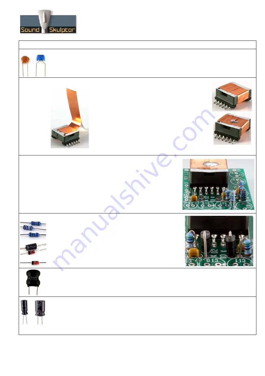
4. Copper shorted turn
In order to reduce the transformer radiations we will add a
copper foil turn around the outside of the transformer.
Start by redrawing the dot on the top of the transformer, a
little further in the corner because the original will be hidden
by the foil.
Partially remove the backing tape from the adhesive copper
foil and place it on the top of the transformer, as shown on
the picture. Make a full while removing the backing tape.
Solder the two ends to electrically close the loop.
5. Transformer soldering
Apply a small quantity of solder on one of the transformer PCB
pads.
Position the transformer, making sure the dot is in the correct
place and reflow the pad solder to lock the transformer. Adjust
until all the transformer pins are all well centred on their respective
pad. Solder one pin on the opposite row. When the position is
correct, solder all the pins.
6. Resistor R7 & diodes D2, D3
Add R7 and diodes D2, D3.
The R7 silk-screen writing is hidden by the transformer. It is
adjacent to C7 and D2.
The diodes are also placed vertically, cathode on top. Bend the
cathode lead (marked by a ring on the diode body).
Warning
: Make sure to respect the direction of the diodes. The
cathode side is marked by a K on the PCB.
7. Radial inductors
Add L2, L3.
8. Electrolytic capacitors
Add C1, C2, C10 to C13.
Solder one lead first, adjust verticality then solder the second lead.
Warning
: The +lead must go into the +hole. Do not reverse (they may explode !)
Warning
: Make sure the caps are inserted as low as possible because they define the height of the
module.
Copyright ©2013 to Today SoundSkulptor