www.soundskulptor.com
Document revision 1.3 – Last modification : 09/10/14
Switcher-2 Assembly guide – Main PCB
12. Spacer
Stick the rubber spacer on the Switcher3 PCB,
at the position shown on the picture, between
the solder pads.
Switcher-2 Quick testing
The switcher can be tested directly in the SK501 module but it is a good idea to check it alone if you can. What you
need is a 12V DC source and a voltmeter.
Connect the 12V source between the (+12)
and (0V) supply pins (near transformer) and
connect the voltmeter between the (0) and
(+) pins on the output side.
After powering, you should read
+19 to 20Volts on the (+) pin,
-19 to -20Volts on the (-) pin,
The full test requires pulling current and will be
done in the MC624.
Switcher-2 Assembly guide – Shield
1. PCB split
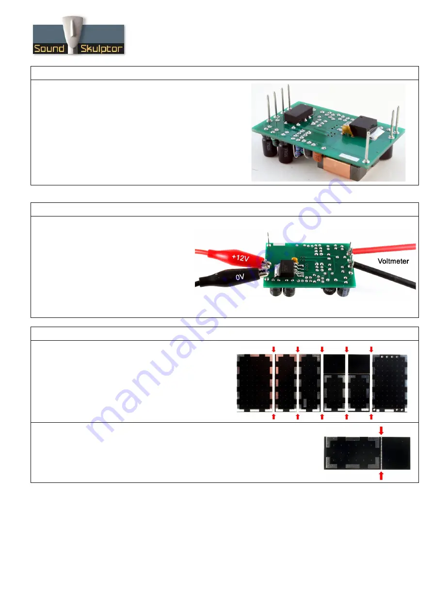
Split the shield PCB into 6 pieces.
2. PCB split
Break the 2 sides along the hole line and smooth out the jagged side by rubbing it on
a piece of sand paper.
Copyright ©2013 to Today SoundSkulptor


