background image

90 | Service Manual: FUSION EQUINE 
DR®


4. Configuring the FUSION EQUINE DR

® 

X-ray 

System


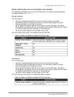
Valid configuration characters 

The following table lists the characters that may be used to configure DICOM attributes. 

Table 46: Valid characters for DICOM configuration 


0-9 

A-Z 

a-z 

<space> 

‘ 

‘ 


Configuring general DICOM settings


The digital radiography system can communicate onsite and remotely with DICOM devices such as 
storage devices and worklists. 


About this task


Warning: 

It is the responsibility of the Service Tech or the site 

network administrator to ensure that DICOM devices and the network 
are configured properly to work with the digital radiography system. 
Improper configuration can result in failures in sending images 
acquired by the digital radiography system. 

Il est de la responsabilité de la Tech de service ou à l'administrateur 
réseau de site pour s'assurer que les dispositifs DICOM et le réseau 
sont correctement configurés pour fonctionner avec le système x - 
ray. Une mauvaise configuration peut entraîner des défaillances dans 
l'envoi d'images acquises par le système x -ray. 


Procedure


1. 

Open the 

Management 

screen. See the topic, 

Displaying the Management screen 

on page 

64, for instructions. 

2. 

Click 

DICOM

The 

General 

tab is displayed by default. 

Summary of Contents for FUSION Equine DR II

Page 1: ...Service Manual Supports the Canon AX B2735W or B3543W panel Non integrated with x ray generator SM0005 Rev A FUSION Equine DR II ...

Page 2: ... 2022 Sound company All rights reserved This page left blank intentionally ...

Page 3: ...er devices this product meets all the rules of IEC 60601 1 Clause 16 Statement of Intended Use The FUSION EQUINE DR II digital radiography imaging system is a high resolution digital imaging system intended to replace conventional film techniques or existing digital systems in multipurpose or dedicated applications specified below The digital radiography imaging system enables an operator to acqui...

Page 4: ...r entered manually When the user has finished applying processing annotation and measurement features of Sound SmartDR Premier software the images can be archived or printed to appropriate DICOM compliant devices Intended User Profile The digital radiography system is intended for use in general radiographic examinations and applications excluding fluoroscopy by a veterinary technologist or other ...

Page 5: ...USION EQUINE DR II is a registered trademark of Sound Technologies Inc The Intel Core i5 Processor is a trademark of Intel Santa Clara Calif The Dual Band Wireless AC 7260 is a product of Intel Windows is a registered trademark of Microsoft Corporation in the United States and other countries AX B2735W and AX B3543W panels Canon name and Canon logo are trademarks or brand names of Canon Inc All ot...

Page 6: ...ual This manual together with Sound Technologies Inc training gives radiologic technologists the step by step instructions that they need to acquire review and store images with the digital radiography system UM0005 FUSION EQUINE DR II Service Manual This manual combined with manufacturer provided training classes supplies the information that a service technician requires to set up configure cali...

Page 7: ...ision History The following table shows when this document has been revised and a description of the major updates for each revision Table 2 Document revisions Revision letter Issue date ECO number Changes made A 12 29 2021 Initial release ...

Page 8: ... information ISO 15223 1 2012 5 4 4 Warning General warning IEC 60601 1 2012 Table D 2 No 2 Read accompanying documents or instructions for use IEC 60601 1 2005 Table D 2 No 10 The date of manufacture is adjacent to this symbol ISO 15223 1 2012 5 1 3 The manufacturer s serial number is displayed with this symbol ISO 15223 1 2012 5 1 7 The procedure requires making X ray exposures and producing rad...

Page 9: ... radiation Indicates elevated or potentially hazardous levels on non ionizing electromagnetic radiation IEC 60417 5140 The manufacturer s catalog number model number is displayed with this symbol ISO 15223 1 2012 5 1 6 The name and address of the manufacturer is displayed with this symbol The date of manufacture may also be included with this information ISO 15223 1 2012 5 1 1 ...

Page 10: ......

Page 11: ...on AX Series battery charger specifications 15 Canon Ready Indicator specifications 19 Canon AX B3543W detector specifications 21 System Backup Thumb Drive 23 Software 23 Carrying Cases 23 System storage accessories 26 Chapter 2 Safety Warranty and Licensing Information 30 Pre installation Site Survey 31 Service Technician Training 31 Electromagnetic compatibility 31 Emissions immunity and separat...

Page 12: ... of the FUSION EQUINE DR Software 65 Shutting Down the PC 68 Connecting the X ray Generator 70 Installation Report Form 71 Chapter 4 Configuring the FUSION EQUINE DR System 73 Configuring the X ray Generator 74 Displaying the Management screen 74 Configuring Basic Options 75 Configuring Intermediate Options 77 Configuring Advanced Options 79 Site Information 81 Configuring Panels 81 DICOM Storage ...

Page 13: ...the Digital Radiography System 144 Chapter 6 Diagnostics 146 Verifying Application Version Information 147 Log Files 147 Collecting Data 149 Viewing Panel Software Versions 151 Diagnosing WiFi Connection Issues 152 Chapter 7 Access Help 155 Help Options window 156 Appendix A Technical Support 159 Locating the System Serial Number 160 ...

Page 14: ...Equine DR II Backpack 24 Figure 16 SOUND Equine 14x17 bag 25 Figure 17 SOUND Equine 14x17 bag panel and storage area 25 Figure 18 Neoprene Panel Cover for AX B2735W 26 Figure 19 Neoprene Panel Cover for AX B3543W 26 Figure 20 Sound custom frame for the AX B2735W 27 Figure 21 AX B3543W Frame Side View 27 Figure 22 AX B2735W Frame Top View 28 Figure 23 Detector Tunnel Podoblock for the AX B2735W Pan...

Page 15: ...on detected 97 Figure 52 New crop region selected 97 Figure 53 Properly detected cropping region 97 Figure 54 Acq Profiles Protocols tab 99 Figure 55 Acq Profiles Protocols tab new protocol 100 Figure 56 Acq Profiles screen Protocols tab species selected 100 Figure 57 Acq Profiles Protocols tab region selected 101 Figure 58 Acq Profiles Protocols tab anatomy selected 101 Figure 59 Acq Profiles Pro...

Page 16: ...gure 76 Overlay preview with data Landscape 117 Figure 77 Overlay preview with data Portrait 117 Figure 78 Backup tab 121 Figure 79 Restore tab 122 Figure 80 Update tab 126 Figure 81 Versions tab 147 Figure 82 Logs window 148 Figure 83 Help Options window 155 Figure 84 Access the Sound Experience Support Portal 156 Figure 85 Suggest a Feature 156 Figure 86 Suggest a Feature 156 ...

Page 17: ...6 Table 15 AX Series single bay battery charger part name sand functions 16 Table 16 Canon AX Series battery charger technical specifications 18 Table 17 Ready Indicator part names and functions 19 Table 18 Canon AX B3543W X Ray detector technical specifications 22 Table 19 AX B3543W RF Transmitter specifications 23 Table 20 Emissions FUSION EQUINE DR II equipment and systems 33 Table 21 Electroma...

Page 18: ...ries single bay battery charger charge status 55 Table 40 Troubleshooting the battery charger 56 Table 41 Troubleshooting the single bay battery charger 58 Table 42 Basic configuration options 76 Table 43 Intermediate Configuration Options 78 Table 44 Advanced Configuration Options 80 Table 45 Network profile settings 86 Table 46 Valid characters for DICOM configuration 90 Table 47 DICOM General c...

Page 19: ...ents Hardware Part Numbers on page 2 SOUND 14 TABLET Tablet on page 4 AX B2735W X ray Panel Technical Specifications on page 9 AX B3543Wv4 detector specifications on page 21 System Backup Thumb Drive on page 23 Software on page 23 System storage accessories on page 26 ...

Page 20: ...omponents Details Part number Sound 14 Tablet PC Included Windows 10 Enterprise SmartDR Premier Software SmartPACS Software Sound SMART DR Recovery Media Kit Digital Pen AC DC Power Adapter and AC cord 20 900 Canon AX B2735W CsI panel detector The panel comes with two batteries 91 444 Canon AX B3543W CsI panel detector The panel comes with two batteries 91 445 Canon dual bay battery charger 10 137...

Page 21: ...let AX B2735W panel AX B3543W panel panel batteries and accessories 70 798 Sound Equine 1417 Bag Protective bag for storage of the AX B3543W panel panel batteries and accessories 70 801 Neoprene panel cover for 11x14 panel Accommodates AX B3543W panel 70 805 Neoprene panel cover for 14x17 panel Accommodates AX B3543W panel 70 882 Panel 11x14 detector tunnel Accommodates AX B2735W with podoblock 70...

Page 22: ...ve SSD 8GB RAM Built in Wi Fi Intel AC 8265 and Bluetooth 1920 x 1080 pixels 1000 nits high brightness capacitive touch display 2 60W battery packs Micro SD Card Slot Figure 1 Sound 14 Tablet Sound 14 Tablet technical specifications Table 6 SOUND 14 Tablet technical specifications Parameter Description CPU Intel 8th Generation Core i5 8250U quad core 1 6 GHz processor RAM 8GB Storage 1TB solid sta...

Page 23: ...0W Enclosure ABS PC plastics and magnesium aluminum alloy Dimensions H x W x D 9 6in x 13 8in x 1 16 in 244mm x 244mm x 29 5mm Weight 6 38lbs 2 9kg Vibration and Shock Resistance MIL STD 810G EMI and EMC Tolerance MIL STD 461F Water and Dust Resistance IP65 Regulatory FCC Class B CE RoHS compliant Temperature Operating 20 C to 60 C 4 F to 140 F 1 Storage 55 C to 70 C 67 F to 158 Humidity 0 90 non ...

Page 24: ...d connectors Item Description 1 Ethernet port RJ 45 2 USB 3 0 port 3 HDMI output 4 Audio jack 5 Power LED Blue battery is 25 100 charged Blinking blue battery is charging Orange battery is 11 25 charged Blinking orange battery is below 10 charged 6 Power button Press to power the tablet on or off 7 Programmable buttons 8 USB 3 0 ports 9 DC input Connect to AC DC power adaptor to charge or power th...

Page 25: ...ND 14 Tablet and AC DC adaptor Connect the AC DC adaptor to the tablet at the DC input and to a wall outlet to power tablet or charge the tablet s batteries Figure 4 Battery latch locations on SOUND 14 Tablet To remove the battery push the switch on the latch to unlock it Then slide the latch to remove the battery ...

Page 26: ... 8 Bluetooth keyboard specifications Parameter Description Dimensions 158mm x 101mm x 13mm folded 320 06mm x 101 99mm x 5 8mm unfolded Weight 176g Battery Rechargeable lithium ion battery Battery life 40 hours of uninterrupted work continuous typing 30 days in standby mode Connections Micro USB charging cable included Bluetooth 3 0 backward forward compatible Operating distance 10 m 32 ft Indicato...

Page 27: ...735W Detector Specifications The FUSION EQUINE DR II system can include the AX B2735W x ray panel The x ray panel comes with the following components battery battery charger ready indicator Figure 6 AX B2735W physical dimensions Figure 7 AX B2735W physical dimensions ...

Page 28: ...10 Service Manual FUSION EQUINE DR II 1 System Overview Table 9 AX B2735W technical specifications ...

Page 29: ...Service Manual FUSION EQUINE DR II 11 1 System Overview Table 10 Canon AX B2735W Series Panel part names and functions ...

Page 30: ...12 Service Manual FUSION EQUINE DR II 1 System Overview Table 11 Canon AX B2735W Wireless Communications ...

Page 31: ...Service Manual FUSION EQUINE DR II 13 1 System Overview Table 12 Canon AX Series Panel Battery Specifications ...

Page 32: ...14 Service Manual FUSION EQUINE DR II 1 System Overview Figure 8 Attaching and removing the battery pack for the AX Series ...

Page 33: ...Service Manual FUSION EQUINE DR II 15 1 System Overview Figure 9 AX Series battery charger dimensions Table 13 AX Series battery charger part name and functions ...

Page 34: ...16 Service Manual FUSION EQUINE DR II 1 System Overview Table 14 AX Series battery charger technical specifications Table 15 AX Series single bay battery charger part names and functions ...

Page 35: ...Service Manual FUSION EQUINE DR II 17 1 System Overview ...

Page 36: ...18 Service Manual FUSION EQUINE DR II 1 System Overview Table 16 Canon AX Series battery charger technical specifications ...

Page 37: ...Service Manual FUSION EQUINE DR II 19 1 System Overview Table 17 Ready Indicator part names and functions ...

Page 38: ...20 Service Manual FUSION EQUINE DR II 1 System Overview Figure 10 Ready Indicator dimensions ...

Page 39: ...SION EQUINE DR II 21 Canon AX B3543W detector specifications Review the specifications for the detector before installing configuring or using the detector Figure 11 Canon AX B3543W Figure 12 Canon AX B3543W detector physical dimensions ...

Page 40: ...22 Service Manual FUSION EQUINE DR II 1 System Overview Table 18 Canon AX B3543W X Ray detector technical specifications ...

Page 41: ...orted for use with this digital radiography system Windows 10 Enterprise IoT Sound SmartDR Premier Sound Smart PACS 1 7 MusicaVET Carrying Cases You may choose to store the Sound system in the carrying cases described in this section The hard side carrying case accommodates Sound 14 Tablet AX B2735W and two batteries for the panel with Canon Flat Battery charger Sound Equine Backpack accommodates ...

Page 42: ... Backpack accommodates Sound 14 Tablet AX B2735W Panel Two panel batteries Power supply and cable for tablet Extra accessories Sound Equine Backpack You may choose to store the Sound system in the backpack described in this section The backpack accommodates the Sound 14 Tablet the AX B2735W and AX B3543W panel detectors and two batteries for the AX Series panel detectors Figure 15 FUSION EQUINE DR...

Page 43: ... system in the 14x17 bag described in this section The bag accommodates the Sound 14 Tablet the AX B2735W and AX B3543W panel detectors and two batteries for the AX Series panel detectors Figure 16 Sound Equine 14x17 Bag showing panel 1 and battery 2 storage areas Figure 17 The FUSION 1417 bag panel storage area ...

Page 44: ...age cases you may choose to include one or more of the accessories described in this section to store FUSION EQUINE DR II system components Neoprene Panel Cover The neoprene panel cover protects the panel detector Figure 18 Neoprene Panel Cover for AX B2735W Panel Figure 19 Neoprene Panel Cover for AX B3543W Panel ...

Page 45: ...1 System Overview Service Manual FUSION EQUINE DR II 27 Sound Panel Frame and Handle Figure 20 Sound custom frame for the AX B3543W Panel Figure 21 AX B3543W Frame Side View Connector Power Button LEDs ...

Page 46: ...System Overview Figure 22 AX B3543W Frame Top View Detector Tunnel Podoblock The Detector Tunnel Podoblock for the AX Series offers another storage option Figure 23 Detector Tunnel Podoblock for the AX B2743W panel Connector Power Button LEDs ...

Page 47: ...otation The new improved tablet cradle release locking feature provides the user to quickly easily release the top lid tablet cradle assembly to position the tablet height and use the rotation feature of the cradle assembly so it can be used in landscape and or portrait mode Figure 25 Cradle Release Label and Tablet Rotation ...

Page 48: ...c Radiated Power for mobile tablet 2 4G WIFI on page 35 Effective Isotropic Radiated Power for mobile tablet 5 2G WIFI on page 37 Effective Isotropic Radiated Power for mobile tablet 5 8G WIFI on page 39 Equipment Classification on page 41 Inspecting Components on page 41 Mechanical Safety on page 42 Electrical Safety on page 43 Software Safety and Use on page 44 Operator Safety on page 44 Service...

Page 49: ...ur products assess the facilities into which the digital radiography system will be installed We give them a short form the Pre installation Site Survey to complete They submit the Survey to Sound Technologies Inc and it helps us to send the correct equipment and configuration This survey is helpful to the installer of the system too Therefore if you do not have the completed version of the Pre in...

Page 50: ...particulières pour maintenir la compatibilité électromagnétique Le système doit être installé et mis en service conformément aux informations EMC fournies dans ce document Les équipements de communication RF portables et mobiles peuvent affecter les équipements électromédicaux Caution Failure to avoid RF interference while operating FUSION EQUINE DR may cause failure of the digital imaging system ...

Page 51: ...ns CISPR 11 Group 1 FUSION EQUINE DR uses RF energy only for its internal function therefore its RF emissions are very low and unlikely to cause any interference in nearby electronic equipment RF emissions CISPR 11 Class A or B Class A Harmonics IEC 61000 3 2 Class A B C D or NA Class A Flicker IEC 61000 3 3 Complies or NA Complies FUSION EQUINE DR is suitable for use in all establishments other t...

Page 52: ... operation during power mains interruptions it is recommended that the system be powered from an uninterruptible power supply or battery Power frequency 50 60 Hz magnetic field EN IEC 61000 4 8 30 A m 30 A m Power frequency magnetic fields should be that of a typical commercial or hospital environment Table 22 Immunity All equipment and systems not life supporting Emissions test EN IEC 60601 test ...

Page 53: ...eparation m 150 kHz to 80 MHz D 3 5 V1 P Separation m 80 to 800 MHz D 3 5 E1 P Separation m 800 MHz to 2 5 0 GHz D 7 E1 P 0 01 0 11667 0 11667 0 23333 0 1 0 36894 0 36894 0 73785 1 1 1667 1 1667 2 3333 10 3 6894 3 6894 7 3785 100 11 667 11 667 23 3333 Effective Isotropic Radiated Power for mobile tablet 2 4G WIFI These Effective Isotropic Radiated Power EIRP values apply to the mobile tablet EIRP ...

Page 54: ... ANT1 ANT2 20 2412 12 34 12 28 2442 12 53 12 69 2472 13 00 12 82 25 11 4 2412 12 25 12 37 2442 12 56 12 78 2472 12 76 12 60 45 11 4 2412 12 24 12 23 2442 12 73 12 75 2472 12 70 12 82 Table 26 EIRP 802 11n 20MHz Transmitter Temp C Power Supplied VDC Frequency MHz RF Output Power EIRP dBm Limit 20 11 4 ANT1 ANT2 ANT1 ANT220 2412 12 38 12 34 15 37 2442 12 59 12 70 15 66 2472 12 65 13 04 15 86 25 11 4...

Page 55: ...4 2422 11 28 11 34 14 32 2442 11 52 11 52 14 53 2462 12 00 11 78 14 90 45 11 4 2422 11 34 11 44 14 40 2442 11 60 11 59 14 61 2462 12 08 11 74 14 92 Effective Isotropic Radiated Power for mobile tablet 5 2G WIFI These Effective Isotropic Radiated Power EIRP values apply to the mobile tablet EIRP is the maximum radiated power of the transmitter and its antenna RF Output Power 5180MHz 802 11a 5 2G WI...

Page 56: ...0 10 3 11 39 11 39 14 40 11 4 11 59 11 54 14 58 12 5 12 20 11 83 15 03 25 10 3 11 41 11 30 14 37 11 4 11 65 11 54 14 61 12 5 12 18 11 81 15 01 45 10 3 11 39 11 35 14 38 11 4 11 51 11 55 14 54 12 5 12 18 11 91 15 06 Table 30 RF Output Power 5190MHz 802 11n 40MHz Temperature C Voltage Vdc RF Output Power EIRP dBm Limit dBm ANT1 ANT2 ANT1 ANT2 23 20 10 3 10 26 10 25 13 27 11 4 10 70 10 64 13 68 12 5 ...

Page 57: ...ese Effective Isotropic Radiated Power EIRP values apply to the mobile tablet EIRP is the maximum radiated power of the transmitter and its antenna Table 32 EIRP 802 11a Transmitter Temp C Power Supplied VDC Test Result EIRP dBm Limit Channel 149 Channel 157 Channel 165 ANT1 ANT2 ANT1 ANT2 ANT1 ANT2 20 10 3 10 21 10 31 10 23 10 27 10 22 10 28 14 11 4 10 51 10 72 10 70 10 61 10 74 10 73 12 5 11 01 ...

Page 58: ...9 48 9 77 12 64 12 5 9 73 9 77 12 76 9 67 10 19 12 95 9 74 9 96 12 86 45 10 3 9 19 9 46 12 34 9 23 9 35 12 30 9 40 9 39 12 41 11 4 9 56 9 80 12 69 9 79 9 73 12 77 9 49 9 62 12 57 12 5 9 85 9 85 12 86 9 65 10 07 12 88 9 78 10 00 12 90 Table 34 EIRP 802 11n40 Transmitter Temp C Power Supplied VDC Test Result EIRP dBm Limit Channel 151 Channel 159 T2 ANT1 ANT2 ANT1 ANT2 ANT1 ANT2 ANT1 AN 20 10 3 8 36...

Page 59: ...radiography system has the following equipment classification Protection against electric shock class I Degree of protection against electric shock type B Degree of protection against ingress of water Ordinary Mode of operation Continuous Inspecting Components Ensure that the system components are received in good condition About this task The digital radiography system may be shipped in several b...

Page 60: ...pecial handling including extensive acclimatization times Review the information about the detector in the pertinent chapter of this manual and the documentation that accompanies the detector What to do next After installation take extra precautions to verify the normal operation of the configuration used at the site Mechanical Safety Use only cabling and mounting hardware included with the digita...

Page 61: ...hé Avant d effectuer tout travail à l intérieur des enceintes de composants du système x ray attendez au moins 60 secondes après avoir retiré le câble d alimentation CA pour une décharge complète Components inside enclosures of the digital radiography system are sensitive to electrostatic discharge ESD Personnel servicing components of the digital radiography system must take appropriate ESD preve...

Page 62: ...lure to adequately ensure safety grounding may result in injury to users or patients or fire or other damage to equipment Software Safety and Use Do not install any software that is not explicitly approved by Sound Technologies Inc Unauthorized software may disrupt the processes or resources required by the digital radiography system software and result in abnormal system operation Do not add or r...

Page 63: ... manual and in the User Manual Failure to abide by the instructions and precautions provided in this manual may result in unnecessary risk to patients users or equipment Service Safety Only trained personnel are authorized to service or maintain the digital radiography system and related equipment Failure to obtain training prior to servicing the digital radiography system may result in support ch...

Page 64: ... when the x ray equipment is in use Take appropriate measures to pent the spilling of liquids or bodily fluids on or into the components of the digital radiography system Do not block or restrict the airflow into or out of the computer the detector control unit CP2 or the enclosure around the detector if applicable Adequate air cooling is required to pent overheating of the components inside these...

Page 65: ...ration of FUSION EQUINE DR II s equipment at ambient temperatures below 41ºF or above 95ºF 5ºC 35Cº or at other abnormal conditions Ambient operating temperature for the isolation transformer if used is 32 113ºF 0 45ºC Consult later chapters in this manual or other manufacturers documents for operating conditions of imaging devices Use of any software other than that supplied or approved by seller...

Page 66: ...any other equipment or parts to the digital radiography system without authorization by the seller Faire aucune tentative pour raccorder tout autre appareil ou des parties du système Sound Technologies Inc sans autorisation par le vendeur Environmental safety All components of the digital radiography system must be stored transported installed and operated in accordance with the environmental cond...

Page 67: ...vice Manual FUSION EQUINE DR 49 2 Safety Warranty and Licensing Information Action Temperature Humidity Air pressure Operation 50 90ºF 10 32Cº 30 75 Non condensing 700 hPa 1060 hPa 10 15 lb in2 0 7 1 0 atm ...

Page 68: ...stalling the AX B2735W Panel on page 61 Installing the AX B3543W Panel on page 61 Non integrated X ray Generator on page 61 Power up the System on page 64 Logging In to the Sound User Account on page 65 Logging in to the Windows Administrator Account on page 65 Logging Out of the FUSION EQUINE DR Software on page 65 Shutting Down the PC on page 68 Connecting the X ray Generator on page 70 Installa...

Page 69: ...rce You can operate the tablet while it charges See SOUND 14 TABLET controls indicators and connectors on page 6 for more information 2 Charge the panel battery See Charging the AX B2735W panel battery on page 51 See Charging the AX B3543W detector batteries on page 51 Charging the AX B2735W and AX B3543W batteries Note The use of accessories batteries battery chargers or cables other than those s...

Page 70: ... liquide de soufflage ou d immersion sur le récepteur la batterie le compartiment des piles ou le chargeur de batterie Ne pas stériliser Caution Do not attempt to insert objects other than the battery into the charger bay Caution N essayez pas d insérer des objets autres que la batterie dans la baie du chargeur Caution Use the battery charger only with the supplied power supply and power cord Caut...

Page 71: ...Service Manual FUSION EQUINE DR II 53 3 Installing the FUSION EQUINE DR II System Figure 26 AX Series battery charger operating procedures Table 38 AX Series battery charger charge status ...

Page 72: ...54 Service Manual FUSION EQUINE DR 3 Installing the FUSION EQUINE DR II X ray System Figure 27 AX Series single bay battery charger operating procedures ...

Page 73: ...Service Manual FUSION EQUINE DR II 55 3 Installing the FUSION EQUINE DR II System Table 39 AX Series single bay battery charger charge status ...

Page 74: ...56 Service Manual FUSION EQUINE DR 3 Installing the FUSION EQUINE DR II X ray System Troubleshooting the Battery Charger Table 40 Troubleshooting the battery charger ...

Page 75: ...Service Manual FUSION EQUINE DR II 57 3 Installing the FUSION EQUINE DR II System ...

Page 76: ...58 Service Manual FUSION EQUINE DR 3 Installing the FUSION EQUINE DR II X ray System Table 41 Troubleshooting the single bay battery charger ...

Page 77: ...Service Manual FUSION EQUINE DR II 59 3 Installing the FUSION EQUINE DR II System ...

Page 78: ...60 Service Manual FUSION EQUINE DR 3 Installing the FUSION EQUINE DR II X ray System Attaching or Removing the battery pack Figure 28 Procedure to remove or attach the AX Series panel battery pack ...

Page 79: ...Optional Install the neoprene cover over the panel Installing the AX B3543W panel The AX B3543W panel is a lightweight and portable digital X ray imaging device for radiographic use but not for human diagnostic use Procedure 1 Remove the panel from the carrying case 2 Attach a fully charged battery pack in the AX B3543W panel See Attaching or Removing the battery pack on page 52 3 Optional Install...

Page 80: ...iagram for the AX B2735W panel The following diagram shows the connections between the main components of the digital radiography system Figure 29 Connection diagram AX B2735W panel Sound 14 Tablet and AX B2735W Panel connected through WiFi Sound 14 Tablet and DICOM Send PACS connected through WiFi ...

Page 81: ...gram for the AX B3543W panel The following diagram shows the connections between the main components of the digital radiography system Figure 30 Connection diagram AX B3543W panel Sound 14 Tablet and AX B3543W Panel connected through WiFi Sound 14 Tablet and DICOM Send PACS connected through WiFi ...

Page 82: ... ou explosive y compris certains gaz utilisés pour l anesthésie Les moteurs électriques et autres équipements électriques dans ou liés au système à rayons X peuvent enflammer des gaz ou des vapeurs inflammables ou explosifs entraînant des blessures la mort ou des dommages Consulter la documentation du site ou le personnel pour déterminer la présence et les dangers des gaz à proximité du système à ...

Page 83: ...rt the PC The PC automatically logs in to the Sound account and starts the Sound SmartDR Premier software Logging in to the Windows Administrator Account The Windows Administrator account provides full access to the operating system and is useful for some service related tasks Procedure 1 If the PC is not already on power it up and allow it to log into the Sound account and start the software 2 Pr...

Page 84: ...le but have not been installed you must complete this process twice to log off of the system Procedure 1 From the Home Screen click on the hamburger menu located on the upper right corner Figure 31 Sound SmartDR Premier Software Home Screen 2 Select Log Out from the drop down list Figure 32 Sound SmartDR Premier Software drop down menu ...

Page 85: ... Click on OK to Log Out 4 Click on EXIT to close the FUSION DR screen 5 The following messages are displayed before the software closes to display the Windows desktop IMPORTANT The Sound SmartDR Premier software automatically backup the database if you log off or shutdown the software ...

Page 86: ...e shut down automatically on logging off of the PC About this task Note If system updates are available but have not been installed you must complete this process twice to shut down the system Procedure 1 From the Home Screen click on the hamburger menu located on the upper right corner 2 From the drop down menu click on SHUTDOWN ...

Page 87: ... System 3 At the prompt click on OK to shut down the system 4 The following messages are displayed before the software closes to display the Windows desktop IMPORTANT The Sound SmartDR Premier software automatically backup the database if you log off or shutdown the software ...

Page 88: ...rator There are no physical connections to the x ray generator Procedure Ensure that both the x ray generator and the panel are on and refer to the x ray generator documentation Note When you configure the x ray generator the exposure window must always be set to less than the panel integration window 1 second ...

Page 89: ...lation New Reinstalled Used Date 20 System serial number Site information Distributor information Name Name Street Street City State Zip City State Zip Department administrator Service engineer Phone Phone Email Email Survey completed by print Signed Date Room configuration Bucky replacement Chest stand Table Positioner type Make Model High resolution monitor type Make Model Control station in Exa...

Page 90: ...ce Manual FUSION EQUINE DR 3 Installing the FUSION EQUINE DR II X ray System Mfr and model of second panel if any Wireless Yes No X ray generator Manufacturer Model Integrated with the DR system Wireless Yes No ...

Page 91: ... screen on page 74 Configuring Basic Options on page 75 Configuring Intermediate Options on page 77 Configuring Advanced Options on page 79 Site Information on page 81 Configuring Panels on page 81 DICOM Storage Devices on page 89 Configuring Acquisition Profiles on page 94 Managing Users on page 104 Configuring Logging on page 113 Customizing Overlays on page 115 ...

Page 92: ...tion Profiles on page 97 for instructions Note For most sites the default acquisition profiles are sufficient and no configuration is required 8 Manage users See the topic Managing Users on page 106 for instructions 9 Configure logs See the topic Log Files on page 144 for information about log file options 10 Customize overlays See the topic Customizing Overlays on page 116 for instructions 11 Sel...

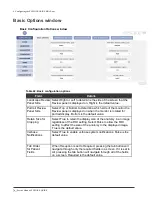
Page 93: ...3 Location of Hamburger icon The Management screen opens and you can complete your maintenance and configuration tasks The user type that is logged into the system controls the tasks that you can perform Figure 34 Management screen Configuring Basic Options Configuring the System Options is the first step in configuring the digital radiography system Procedure 1 Open the Management screen See the ...

Page 94: ...r is rotated for portrait display Bottom is the default value Retain Size for Cropping Select True to retain the display size of the anatomy in an image regardless of the ROI setting Select False to allow the ROI setting to affect the size of the anatomy in the displayed image True is the default value Verbose Notifications Select True to enable verbose system notifications False is the default va...

Page 95: ...4 and Beep 5 Show Add Study Form Select True to display the Add Study form when you add a study for a patient Select False to allow the system to skip this form and create another study containing the same settings as the previous study set for that patient Measurement Units Set the units for measurements to millimeters mm or centimeters cm Configuring Intermediate Options As part of the system co...

Page 96: ...s can continue the operation or cancel and return to the previous screen Options True or False Default False Generate Patient ID Selecting True in this field causes patient IDs to be automatically generated The default value is False Patient ID Prefix When Generate Patient ID is set to True you can specify an alphanumeric patient ID prefix of up to 10 characters in this field Default Patient Last ...

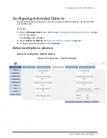
Page 97: ...h as the COM port and I O card Procedure 1 Open the Management screen See the topic Displaying the Management screen onpage 64 for instructions The Config screen displays 2 Select Advanced Options See Advanced Options window on page 69 3 Configure the fields as desired and click Save Advanced Options window Advanced Configuration Options window Figure 35 Config screen Advanced Options ...

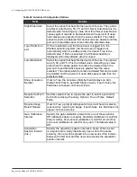
Page 98: ...ed hard disk space is greater than the value selected The oldest patient records are deleted first and records are deleted until the percent of used disk space is less than the selected value Show Accession Number If set to True the Accession Number field displays on Add Patient Edit Patient and Add Study screens If set to false this field does not appear on these screens Require Vet Tech Selectio...

Page 99: ...iguring Panels This chapter describes how to configure the flat panel detectors that are supported for use with this system Procedure 1 Install the Ready Indicator PN 10 426 into the USB port on the Tablet 2 Open the Management screen See the topic Displaying the Management screen onpage 64 for instructions The Config screen is displayed automatically 3 Click the Panel Configuration tab ...

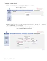
Page 100: ...ctor that you want toinstall Figure 37 Register Detector 5 Enter the SSID information by using the last 5 digits of the serial number of the detector In this instance the last 5 digits of the panel serial is 00001 6 The port will automatically select the COM port the IR Dongle is using Figure 38 Entering SSID and Serial Number ...

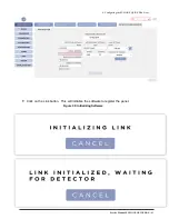
Page 101: ...Service Manual FUSION EQUINE DR 83 4 Configuring the FUSION EQUINE DR X ray System 7 Click on the Link button This will initialize the software to register the panel Figure 39 Initializing Software ...

Page 102: ...nking process is complete the dialog will automatically close The Serial Number field should now be populated with the Detectors Serial Number Figure 40 Completion of Linking Detector 10 Pressing the Register button will show the Detector Registration Dialog and start the registration process The process will start by Identifying the Detector Figure 41 Starting Registration Process ...

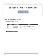
Page 103: ... the system will save the Detector to the Database And the system will Initialize the Link with the Detector Figure 42 Initializing Detector 12 Once the panel has been initialized the registration process is complete Press the Close button to close the Dialog Figure 43 Registration Complete ...

Page 104: ...ration controls Controls for configuring detectors Panel Configuration Controls Control Description Steps Remove Panel Removes the panel from the configuration 1 Select the desired Active Panel 2 Click the subtab 3 Tap Remove Panel and Save Network profile setting Table 45 Network profile settings ...

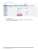
Page 105: ...remove a panel Procedure 1 Open the Management screen See the topic Displaying the Management screen onpage 64 for instructions The Configuration window is displayed automatically 2 Click Panel Configuration The panel that is currently configured with the system is displayed Figure 44 Config screen Panel Configuration Remove Panel button ...

Page 106: ...anual FUSION EQUINE DR 4 Configuring the FUSION EQUINE DR X ray System 3 Click Remove Panel The panel is removed If you add the same panel again you must restart the PC before you can connect to the panel properly ...

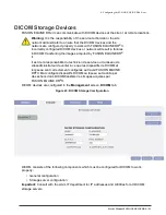
Page 107: ...SION EQUINE DR II Il est de la responsabilité du technicien de service ou du réseau de sitesadministrateur de veiller à ce que les dispositifs de DICOM et le réseau sont correctement configurés au travail FUSION EQUINE DR II Mal configuré dispositifs DICOM ou réseau se traduira par des échecs dans DICOMtransférer les images acquises par FUSION EQUINE DR II DICOM devices are configured in the Manag...

Page 108: ... administrator to ensure that DICOM devices and the network are configured properly to work with the digital radiography system Improper configuration can result in failures in sending images acquired by the digital radiography system Il est de la responsabilité de la Tech de service ou à l administrateur réseau de site pour s assurer que les dispositifs DICOM et le réseau sont correctement config...

Page 109: ...igure the settings as necessary for the site See DICOM Generalconfiguration settings on page 88 for information Figure 46 DICOM General tab DICOM General configuration settings DICOM General tab parameters Figure 47 DICOM General tab Parameters Table 47 DICOM General configuration settings ...

Page 110: ...e default setting is 0 This setting defines how many times a failed network DICOM job will be resent to the DICOM device D Set the Embed Annotations option to True or False True is the default This option can be set to True only if the Process Images option is also set to True When Embed Annotations is set to True all annotations are sent to the DICOM device as part of the image E Set the Time Bet...

Page 111: ...Displaying the Management screen onpage 64 for instructions 2 Click DICOM Storage tab The Storage tab is displayed If no storage servers have been configured the tab is blank as shown in the following image Otherwise the configured storage servers are displayed in the Storage Devices area of the Storage tab Figure 48 DICOM Storage tab 3 Click Add The fields for configuring a new DICOM storage serv...

Page 112: ...cify the port number for the DICOM server connection The default is blank Contact the site IT department or PACS administrator for the IP address of the storage server F Select this check box if you want to automatically send studies and images to the storage server The default is deselected 4 Complete the fields and click Save to save the storage server 5 Optional You can verify the connectivity ...

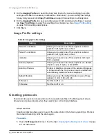
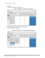
Page 113: ... page 105 for instructions 4 Delete protocols See the topic Deleting protocols on page 105 for instruction Configuring acquisition profile settings Generally the default settings for acquisition profiles meet the needs of the majority of sites Complete this task only if the default settings do not meet the needs of the site About this task Sound and Vet users can modify the image profiles for acqu...

Page 114: ...ct the species region anatomy and shots for which you want to modify the image profile You can add a nickname to any region anatomy or view by right clicking or tapping and holding one of these tiles After you add the nickname it appears in parentheses next to the original name You can remove the nickname by right clicking or tapping and holding the tile and then clearing the nickname from the tex...

Page 115: ...n b To accept click the Crop button in the image control toolbar If you prefer a different region click and drag on the image to create a new box c Release the mouse button When you capture the next image or end the study the system sends only the part of image in the displayed crop region to PACS Figure 51 Incorrect crop region detected Figure 52 New crop region selected The following figure show...

Page 116: ...ptions anterior posterior left right head or foot Laterality Allows you to select one of these options left right both unpaired Autocrop Options Allows you to select one of these options off default chest C spine T spine or small ROI Autocrop Preview Enable or disable a preview of the acquired imageas a full panel with the crop review feature enabled with automatically detected shutters displayed ...

Page 117: ...cq Profiles Protocols tab The Keeneland Repository protocol is configured by default This protocol is used for taking images that can then be submitted to the Keeneland Repository and reviewed digitally by veterinarians at horse auctions It is not for use with the small animal configuration of Sound SMART DR The PennHIP protocol is also provided as a default protocol for use with canines ...

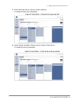
Page 118: ... ray System 3 Click Add A new protocol is added to the Protocols list Figure 55 Acq Profiles Protocols tab new protocol 4 Select the species that you want to use for theprotocol The Select Region list is populated Figure 56 Acq Profiles screen Protocols tab species selected ...

Page 119: ...the region that you want to include inprotocol The Select Anatomy list is populated Figure 57 Acq Profiles Protocols tab region selected 6 Select the part of anatomy that you want to include in the protocol The Select Shots list is populated Figure 58 Acq Profiles Protocols tab anatomy selected ...

Page 120: ...you click on them Figure 59 Acq Profiles Protocols tab shot selected 8 In the Shot List type a name for the Protocol in the Name field The Name field is just above the Shot List 9 If you need to delete a shot from the list select the shot and click the garbage can icon at the top of the Shot List 10 Click Save to save the new protocol Figure 60 Acq Profiles Protocols tab protocol saved ...

Page 121: ... the protocol that you want to edit The protocol details are displayed The name of the protocol can be edited new shots can be added and existing shots can be removed The species may not be changed Figure 61 Acq Profiles Protocols tab edit protocol 4 After your changes are complete click Save Deleting protocols Sound and Vet users can delete image protocols Procedure 1 Open the Management screen S...

Page 122: ...is section review the topic Access levels and privileges Procedure See one of the following topics to complete the desired task Adding users on page 108 Editing users on page 110 Resetting passwords on page 111 Deleting users on page 114 Users privileges and credentials The tasks that you can complete with the digital radiography system are controlled by the type of user that you use to log in to ...

Page 123: ...9 Features and fields accessible to the Vet user type Feature Accessible fields Config System Options Review Panel Side Language Retain Size for Cropping Verbose Notifications Default Species Default Weight Diagnostics Data Collector All Acq Profiles All Users All System All Overlay Editor All Tech access The Tech user type can have a designated default Vet user for each user of this type created ...

Page 124: ...ype of user created for them Prerequisites Review Users privileges and credentials on page 106 to gain a better understanding of the access levels assigned to each user type Procedure 1 Open the Management screen See the topic Displaying the Management screen onpage 64 for instructions 2 Click Users The User window is displayed showing the users that already exist in the system The following figur...

Page 125: ...on for the new user 5 Under Preferences Default user_type select the default user user_type is Vet or Tech depending on the type selected for the new user If Vet is the type selected for the new user you can select a default Tech to be associated with the new Vet user If Tech is the type selected for the new user you can select a default Vet to be associated with the new Tech user The preferences ...

Page 126: ...he top of the screen Figure 65 Users window saved user Editing users After a user has been created you can edit any of the user information and preferences except the username and password About this task Usernames must be deleted and re created to be changed Procedure 1 Open the Management screen See the topic Displaying the Management screen onpage 64 for instructions ...

Page 127: ...s and passwords must be edited through the Windows operating system See Resetting passwords on page 111 for instructions 4 Click Save Resetting passwords User passwords can be reset and changed through the Windows operating system Procedure 1 If you are at the Windows desktop go to the next step If the Sound SmartDR Premier software is running log out of the software The Windows desktop is display...

Page 128: ...UINE DR X ray System 2 Right click the Windows Start button and select Control Panel Figure 67 Windows Start button Figure 68 Windows Start menu Control Panel 3 In the User Accounts window select Manage another account Figure 69 Make changes to your account window ...

Page 129: ...NE DR X ray System 4 In the Manage Accounts window select the user account that you want to change Figure 70 Choose the user you would like to change window 5 In the Make changes to XXX account window select Change the password Figure 71 Make changes to user account ...

Page 130: ...al Figure 72 Change Password window 7 Select the Change password button to save the changes 8 Close the Change an Account window The Windows menu ribbon is hidden again and you remain in the Sound SmartDR Premier software interface Deleting users Users can be deleted in Management screen in the Users tab Procedure 1 Open the Management screen See the topic Displaying the Management screen onpage 6...

Page 131: ...displayed Select the check mark to delete the user Configuring Logging Application and DICOM logging can be configured to use Normal or Verbose modes Prerequisites Before you begin this task review the topic Log Files on page 144 to familiarize yourself with the types of log files and what they capture Procedure 1 Open the Management screen See the topic Displaying the Management screen onpage 64 ...

Page 132: ...Select Logs The logging window is displayed Figure 73 Logs screen 3 Select the tab for the log files that you want to configure and select the configuration options Important Set Sound Application logging to Verbose mode only when instructed to do so by a technical support representative ...

Page 133: ... Editor consists of two main parts the DICOM Tag List and the Layout Grid both of which are displayed to the right The Grid is made up of nine 9 boxes each of which represent an area of the image display screen Procedure Open the Management screen See the topic Displaying the Management screen onpage 64 for instructions 1 Select Overlay Editor The overlay data elements and grid are displayed Figur...

Page 134: ...ect as much or as little data onto the grid as you choose For example the following image shows the Patient Breed Description Patient Orientation Referring Physician and Responsible Person data points have been added to the grid Figure 75 Overlay with data 3 Once you have the desired overlay data inserted click on the Preview button to verify location of the data ...

Page 135: ...Service Manual FUSION EQUINE DR 117 4 Configuring the FUSION EQUINE DR X ray System Figure 76 Overlay preview with data Landscape Figure 77 Overlay preview with data Portrait ...

Page 136: ...zing the overlay and overlay data elements click Save in the Overlay Editor The value for the selected tags will be displayed in the Acquire Review screen when the user selects the Overlay icon in that screen s tool bar Deleting overlay data elements Overlay data elements can be deleted from overlays by Vet and Sound users Procedure 1 Open the Management screen See the topic Displaying the Managem...

Page 137: ...119 4 Configuring the FUSION EQUINE DR X ray System 3 Click the data element that you want to remove from the overlay grid The data attribute window opens 4 In the data attribute window click Delete 1 In the Overlay Editor click Save ...

Page 138: ...Restoring FUSION EQUINE DR Data and Settings on page 122 Restoring the Tablet Hard Drive on page 123 Updating the Sound SMART DR Software with Auto Update on page 125 Windows Operating System Updates on page127 Export Import the System Configurations on page 127 Performing Panel Gain Calibration on page 136 Viewing Gain Calibration History on page 141 Cleaning the Digital radiography System on pag...

Page 139: ... calibration images and other system files Procedure 1 Open the Management screen See the topic Displaying the Management screen onpage 64 for instructions 2 Click System The Backup tab displays Figure 78 Backup Images Selecting this option backs up the image_db folder Location The directory location of the zip file created by the backup process 3 Under Data To Save select the data that you want t...

Page 140: ... is currently logged in 5 Click Backup The backup process creates a zip file called SD1Backup_YYMMDDHHMMSS where YYMMDDHHMMSS is the two digit year month day hour minute and second of the backup Restoring FUSION EQUINE DR II Data andSettings Sound and Vet users can restore a system that has been backed up Procedure 1 Open the Management screen See the topic Displaying the Management screen onpage ...

Page 141: ...ect Restoring the Tablet Hard Drive This topic describes how to restore the SOUND 14 TABLET hard drive from a thumb drive About this task Warning This process permanently overwrites the entire contents of the hard drive Perform this procedure only on a new hard drive or on an existing drive that has suffered critical data corruption Procedure 1 Log out of the FUSION DR software 2 Press the power b...

Page 142: ... Ensure the wireless keyboard and mouse are connected and operational 5 Press the power button on the tablet to power it up The blue LED above the buttonlights 6 During initial boot up press the ESC key repeatedly until the system displays the Configuration screen 7 Select Boot Manager ...

Page 143: ...restart several times during the process Once installation is complete the tablet will power down Updating the Sound SmartDR Premier Software with Auto Update Digital radiography system updates can be installed or not as needed by the site About this task When you log in to the Sound SmartDR PC the software automatically checks for updates If updates are available the following message is displaye...

Page 144: ... Check for Updates to check manually Figure 80 Update tab If you want to install the update select Begin Update 3 If you want to install the update select Begin Update The digital radiography software closes and the update begins automatically A DOS window and the wyUpdate window are displayed When the update is complete the software restarts and a web page is displayed that provides information a...

Page 145: ... Intel PRO 100 driver is updated the connection to the PaxScan x ray panel will no longer work properly Ne pas mettre à jour le pilote Intel PRO 100 de la carte La liste des mises à jour pourrait inclure le processeur Intel PRO 100 carte car le pilote Pleora remplace le pilote Intel pour la PaxScanpanneau Si le PRO 100 pilote Intel est mis à jour la connexion au panneau x ray PaxScan ne fonctionne...

Page 146: ...guration and patient data See Exporting the system configuration and database on page 129 2 Import a backup created by the export process onto another system running the same version of the software See Importing a system configuration on page 132 3 Repair a system configuration using a backup created by the export process See Repairing a system configuration on page 135 Exporting the system confi...

Page 147: ...FUSION EQUINE DR X ray System Advanced Options window 3 Click on Export Name the file and select the desired location you would like to export the FUSION DR configuration settings Ex filename Fusion SNXXXXX Configuration Backup location C Fusion DR Backup ...

Page 148: ... FUSION EQUINE DR 5 Maintaining the FUSION EQUINE DR X ray System 4 Click on Save The following prompts will be displayed 5 Click on Close when the export is completed 6 Verify the file was exported in the file location ...

Page 149: ... tool allows you save system configuration and patient data for transfer to another system Note The process requires that you have a set of backup files created using the System Configuration available to load onto the system Procedure 1 Open the Management screen See the topic Displaying the Management screen on page 64 for instructions The Config screen displays 2 Select Advanced Options See Adv...

Page 150: ...name Fusion SNXXXXX Configuration Backup location C Fusion DR Backup 4 The following window will prompt Acquisition Profile Protocols Configuration Options excluding Site Info and Storage Servers are selected by default Check Site Info Overlay and Users if would like settings to be imported 5 Click on I understand importing will overwrite my existing settings and click on Import ...

Page 151: ...ort is completed 7 The Sound SmartDR Premier software will close and relaunch automatically Panel Data Collection The Sound SmartDR Premier software has the capability to collect the panel data This tool allows you to export and backup the panel data These files can be used for repair and troubleshooting purposes ...

Page 152: ...sion 1 0 of the Sound SmartDR Premier software Note You can use this tool transfer configurations or data between systems running the same version of the software Note Run this application as Administrator Procedure 1 Open the Management screen See the topic Displaying the Management screen onpage 64 for instructions 2 Select the Diag tab The Data Collector screen displays 3 By default System Info...

Page 153: ...FUSION EQUINE DR 135 5 Maintaining the FUSION EQUINE DR X ray System 5 Click on Collect Data 6 Successfully collected data will display in the status window 7 Verify the export by browsing the location backed up files ...

Page 154: ...he active panel Set the gain calibration frequency Config Advanced Options screen The calibration consists on 4 Successful exposures Prerequisites Before you begin this task ensure that the panel is installed configured and active on the x ray system Procedure 1 Open the Management screen See the topic Displaying the Management screen onpage 64 for instructions ...

Page 155: ...s hairs to the panel Note Recommend the collimator light is overlapping the panel by 2 inches to ensure the panel is getting fully exposed d Setup the technique on the generator as a starting point a KVP 68 b mAs 08 Note Technique is used as a reference point Technique maybe need to be increased decreased according to the software 4 Follow the instructions in the screen and select StartCalibration...

Page 156: ...on If the time out occurs cancel and restart the calibration 5 The calibration window will prompt and prepare 6 When the system is ready for an exposure the Tigger button will be enable Click on the Trigger button Note When you hit Trigger you have a 3 to 5 second window to take an exposure If you do not make an exposure during that time frame the calibration will fail Repeat step 6 7 Take an x ra...

Page 157: ...e and determine if the exposure was a success of failure Note Failure of a successful calibration exposure consists on being too high or too low Adjust technique on the generator and retake the calibration shot you have a 3 to 5 second window to take an exposure Successful Calibration Exposure Failed Calibration Exposure ...

Page 158: ...9 Continue taking the calibration exposures by repeating steps 6 and 7 Panel calibration consists of 4 successful exposures 2nd Calibration Exposure 10 When the calibration is complete a message is displayed indicating success or failure 11 Click Close to exit out of Panel Calibration ...

Page 159: ...ct Calib Calibration History Tab is selected by default 3 Calibration History is selected by default 4 Select the Start Date icon In the pop up calendar select the first date in the date range for histories that you want to view 5 Select the End Date icon In pop up calendar select the last date in the date range for histories that you want to view The gain calibration history for the range of date...

Page 160: ...in this task ensure that the panel is installed configured and active on the x ray system Procedure 1 Open the Management screen See the topic Displaying the Management screen on page 64 for instructions 2 Select Calib 3 Click on Start Self Test The software will automatically run the self tests between the software and panel 4 Self Test Finished Success will display when completed 5 Click Close ...

Page 161: ...reen onpage 64 for instructions 2 Select Calib 3 Select Self Test History 4 Select the Start Date icon In the pop up calendar select the first date in the date range for historires that you want to view 5 Select the End Date icon In the pop up calendar Select the last date in the date range for histories that you want to view The self test history for the range of dates you selected is displayed ...

Page 162: ...e manufacturer of the cleaning agent Warning Do not pour or spray liquid directly onto any component of the digital radiography system Apply the cleaning agent to a clean cloth andgently wipe the equipment to clean Warning Ne pas verser ou vaporiser de liquide directement sur l un des composants du système digital radiography Appliquer l agent de nettoyage sur un chiffon propre et essuyez doucemen...

Page 163: ...equipment back on allow at least 15 minutes for the detector subsystem to initialize before attempting to use the digital radiography system for imaging or calibration Removing Dust From Fans and Heatsinks Even in a clinical environment dust and other contaminants accumulate around fans and heatsinks inside the digital radiography system computer Special attention must be paid to these areas so th...

Page 164: ...ervice Manual FUSION EQUINE DR Chapter 6 Diagnostics Contents Verifying Application Version Information on page 147 Log Files on page 147 Collecting Data on page 149 Viewing Panel Software Versions on page 151 Diagnosing WiFi Connection Issues on page 152 ...

Page 165: ...bout this task Version information can be useful for troubleshooting and updating the system Procedure 1 Open the Management screen See Displaying the Management screen on page 64for instructions 2 Click System Versions Version information for software and system components are displayed Figure 81 Versions tab Log Files The digital radiography system captures and saves information about how applic...

Page 166: ...ation Logging is set to Normal as default 2 For increased logging levels click on the drop down menu and select Verbose 3 Click on Save This mode provides additional details for troubleshooting and service purposes WARNING Increasing the logging levels can affect system performance ...

Page 167: ...en on page 64for instructions 2 Click Diag Data Collector 3 By Default System Information Error and Diagnostics Logs and Database are selected Check Panel Data System Information Enable this option to back up system information Error and Diagnostic Enable this option to back up information that can be Logs used to troubleshoot errors and diagnose problems with the system Database Enable this optio...

Page 168: ...4 Selected the desired location you would like to backup these files and click OK Ex C Fusion DR Backup 5 Click on Collect Data 6 Successfully collected data will display in the status window 7 Verify the export by browsing the location backed up files ...

Page 169: ...e panel software version can be useful in diagnosing problems with the panel Procedure 1 Open the Management screen See the topic Displaying the Management screen onpage 64 for instructions 2 Select Diag 3 Select Detector Software Versions and ensure that the version match the following image ...

Page 170: ...i tab settings Table 51 WiFi tab parameters Field Description Valid values Link Quality 0 100 Country Code The country code set on the panel Not applicable Channel The wireless channel set on the panel Default 36 Bandwidth This value is set on the panel Not applicable Full Capacity The maximum panel battery charge measured in mAh as reported by the battery Not applicable Remaining Capacity The cur...

Page 171: ...l FUSION EQUINE DR 153 6 Diagnostics Field Description Valid values Temperature Current panel temperature in degrees Celsius 5 35 C Serial Number The serial number of the installed panel Panel battery Serial Number ...

Page 172: ...4 Configuring the FUSION EQUINE DR X ray System 154 Service Manual FUSION EQUINE DR Chapter 7 Access Help Contents Help Options window on page 156 ...

Page 173: ...ptions window Icon Help Displays tips identifying icons displayed on the current screen Training Accesses training videos that demonstrate how to perform common tasks using the interface Support Portal Accesses the Support Portal See Figure 84 Access the Sound Experience Support Portal on page 155 First time users click Register New Userto set up a login and password Use the portal to chat with So...

Page 174: ...156 Service Manual FUSION EQUINE DR 7 Access Help 7 Access Help Item Descriptions Closes the window Figure 84 Access the Sound Experience Support Portal Figure 85 Suggest a Feature Figure 86 Training ...

Page 175: ...Service Manual FUSION EQUINE DR 157 ...

Page 176: ...158 Service Manual FUSION EQUINE DR 7 Access Help Appendix A Technical Support Contents Locating the System Serial Number on page 160 ...

Page 177: ...ogies Inc 3200 Lionshead Ave Suite 100 Carlsbad CA 92010 USA Website http www soundvet com Locating the System Serial Number When you contact technical support you must provide the serial number of the system for which you are requesting assistance Procedure Open the Management screen select Config Site Information The system serial number is located in the Model Informationsection On the side of ...

Page 178: ... 2022 All Rights Reserved Sound Company 3200 Lionshead Ave Suite 100 Carlsbad CA 92010 USA Main Office 1 800 268 5354 Support 1 800 819 5538 ...

Reviews: