34 | Service Manual: FUSION EQUINE
DR®
2. Safety, Warranty, and Licensing Information
Immunity test
EN/IEC 60601
test level
Compliance
level
Electromagnetic
environment
— guidance
Surge EN/IEC
61000-4-5
±1 kV differential
±2 kV common
±1 kV differential
±2 kV common
Mains power quality
should be that of a typical
commercial or hospital
environment
Voltage dips/
dropout EN/IEC
61000-4-11
>100% drop for
0.5 cycle
At 0°, 45°, 90°,
135°, 180°,
225°, 270°,
315°: 100% dip
for 1 cycles
30% dip for
25/30 cycles
>100% dip for 5
s
>100% drop for
0.5 cycle At 0°,
45°, 90°, 135°,
180°, 225°,
270°, 315°:
100% dip for 1
cycles 30% dip
for 25/30 cycles
>100% dip for 5
s
Mains power quality
should be that of a typical
commercial or hospital
environment If the user of the
system requires continued
operation during power
mains interruptions, it is
recommended that the
system be powered from an
uninterruptible power supply
or battery.
Power frequency
50/60 Hz magnetic
field EN/IEC
61000-4-8
30 A/m
30 A/m
Power frequency magnetic
fields should be that of a
typical commercial or hospital
environment.
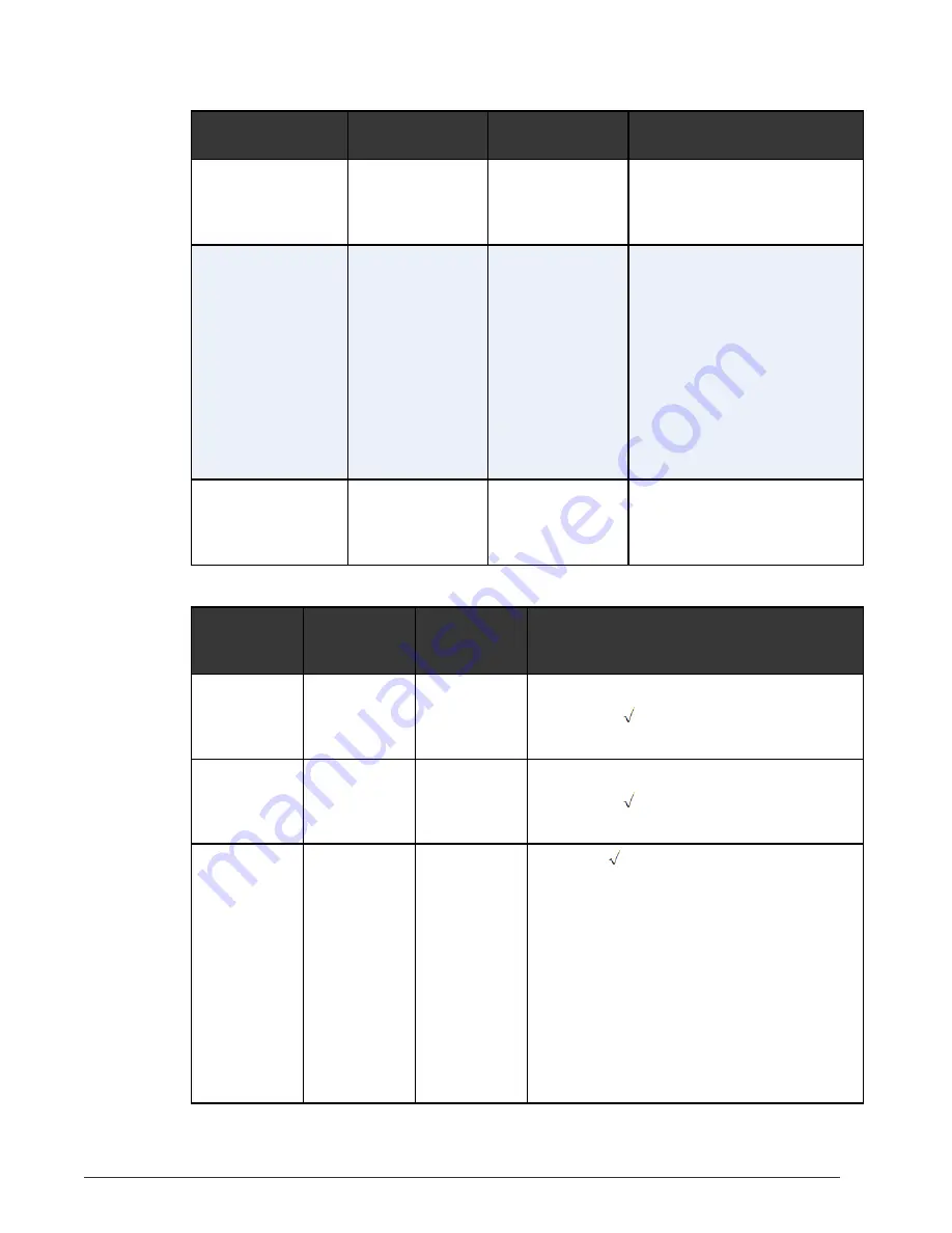
Table 22: Immunity
— All equipment and systems not life-supporting
Emissions
test
EN/IEC
60601
test level
Compliance
level
Electromagnetic
environment
— guidance
Conducted
RF EN/IEC
61000-4-6
3 Vrms
150 kHz
– 80
MHz
(V1)=3Vrms
D=(3.5/V1)( P)
Radiated
RF EN/IEC
61000-4-3
3 V/m
80 MHz
–
2.5 GHz
(E1)=3V/m
D=(3.5/E1)( P) 80 to 800 MHz
D=(7/E1)( P)
800 MHz to 2.5 GHz
Where P = max power in watts and D
= recommended separation distance in
meters.
Field strengths from fixed transmitters,
as determined by an electromagnetic
site survey, should be less than the
compliance levels (V1 and E1).
Interference may occur in the vicinity of
equipment containing a transmitter.
Summary of Contents for FUSION Equine DR II
Page 2: ... 2022 Sound company All rights reserved This page left blank intentionally ...
Page 10: ......
Page 35: ...Service Manual FUSION EQUINE DR II 17 1 System Overview ...
Page 38: ...20 Service Manual FUSION EQUINE DR II 1 System Overview Figure 10 Ready Indicator dimensions ...
Page 75: ...Service Manual FUSION EQUINE DR II 57 3 Installing the FUSION EQUINE DR II System ...
Page 77: ...Service Manual FUSION EQUINE DR II 59 3 Installing the FUSION EQUINE DR II System ...


