,QSXW0RGXOH
Input
1
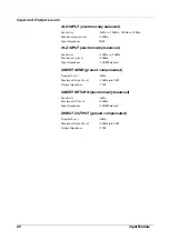
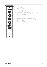
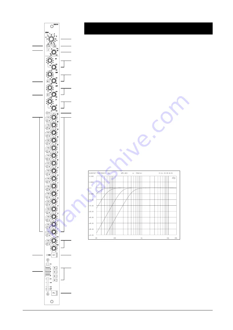
The sensitivity of both the XLR and the HIGH IMPEDANCE (HI-Z jack) inputs
is adjusted by the SENS control. Both inputs are electronically balanced.
XLR input sensitivity: -2dBu to -70dBu, +10dBu to -20dBu (switched range.)
High Impedance input sensitivity: +10dBu to -20dBu
2
When
the
RNGE (Range) switch is depressed the lower sensitivity range of the
input is selected to allow line level signals to be used. The signal is still taken from
the input XLR, unless a jack is inserted into the HI-Z input socket, when the signal
from that is used instead. Note that when the RNGE switch is released the HI-Z
input socket cannot be used.
3
The 48V switch, when depressed, applies 48V phantom power to the
input XLR. An integral red LED in the switch indicates when the phantom power
is on.
4
The
PHASE switch reverses the phase of the selected input.
5
The cutoff frequency of the secondorder highpass filter is varied, between 30Hz
and 400Hz, by the FILTER FREQUENCY control. The filter is deactivated
completely by an integral switch when the pot is fully anticlockwise.
1
2
14
13
5
6
15
19
7
9
11
12
17
3
4
8
10
16
20
18
Equaliser
The EQ section is four band: with shelving sweep high and low frequency sections,
and two peaking sweep mids with switchable Q.
6
The
shelving
HF section has a maximum cut or boost of 15dB and the frequency
is variable between 1kHz and 20kHz.
7
The
peaking
HMF (High Mid) section has a maximum cut or boost of 15dB
and the frequency is variable between 600Hz and 12kHz.
Frequency Response Curves of the High-Pass Filter
16
Input Module
Summary of Contents for SM 16
Page 1: ...SOUNDCRAFT USER GUIDE 16 ...
Page 5: ...Introduction Introduction 1 ...
Page 10: ...6 Introduction ...
Page 11: ...Installation Installation 7 ...
Page 14: ...10 Installation ...
Page 15: ...Module Block Diagrams Module Block Diagrams 11 ...
Page 16: ...PFL BUS GROUPS 1 16 BUSSES R STEREO BUS L STEREO BUS Input Module 12 Module Block Diagrams ...
Page 17: ...Group Output Module Module Block Diagrams 13 ...
Page 18: ...Master Module 14 Module Block Diagrams ...
Page 19: ...Input Module Input Module 15 ...
Page 26: ...22 Input Module ...
Page 27: ...Group Output Module Group Output Module 23 ...
Page 32: ...28 Group Output Module ...
Page 33: ...Master Module Master Module 29 ...
Page 41: ...Appendices Appendices 37 ...


