Stereo Mix
19
The post-fader signal is sent to the stereo mix bus via the L/R (level) and PAN
controls. The PAN control gives a 4.5dB centre drop. The mix bus send is activated
by the ON switch, which has an integral green LED, and may be set pre- or post-fade
by the PRE switch. The pre-fade signal may be sourced from one of the following
three options:
•
post-mute and pre-fade
•
pre-mute
•
pre-EQ and pre-insert
The source selection is done using push-on jumpers.
The factory default is post-mute and pre-fade.
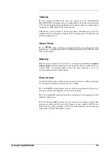
Metering
20
The
red
PEAK LED illuminates when the signal level e14dBu
(internal) at the output of the input amp, the insert return, the output of the EQ or
the post-fader amplifier.
A 16-segment peak-reading bargraph meter in the overbridge meters the signal
directly after the input amplifier. The meter has a peak-reading ballistic
characteristic.
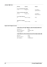
Jumper Options
(RH PCB)
Function
Options
Default
Insert point
post-EQ
J1, J3, J6
jumpers IN for post-EQ
J2, J4, J5
jumpers IN for pre-EQ
Group 1-8 Pre-fade signal
post-mute
J14
jumper IN for pre-EQ & pre-insert
J15
jumper IN for pre-mute
J13
jumper IN for post-mute & pre-fade
Note: only one of the above three jumpers to be fitted at any one time.
Group 9-16 Pre-fade signal
post-mute
J11
jumper IN for pre-EQ & pre-insert
J10
jumper IN for pre-mute
J12
jumper IN for post-mute & pre-fade
Note: only one of the above three jumpers to be fitted at any one time.
Mix L-R Pre-fade signal
post-mute
J8
jumper IN for pre-EQ & pre-insert
J9
jumper IN for pre-mute
J7
jumper IN for post-mute & pre-fade
Note: only one of the above three jumpers to be fitted at any one time.
Input Module
19
Summary of Contents for SM 16
Page 1: ...SOUNDCRAFT USER GUIDE 16 ...
Page 5: ...Introduction Introduction 1 ...
Page 10: ...6 Introduction ...
Page 11: ...Installation Installation 7 ...
Page 14: ...10 Installation ...
Page 15: ...Module Block Diagrams Module Block Diagrams 11 ...
Page 16: ...PFL BUS GROUPS 1 16 BUSSES R STEREO BUS L STEREO BUS Input Module 12 Module Block Diagrams ...
Page 17: ...Group Output Module Module Block Diagrams 13 ...
Page 18: ...Master Module 14 Module Block Diagrams ...
Page 19: ...Input Module Input Module 15 ...
Page 26: ...22 Input Module ...
Page 27: ...Group Output Module Group Output Module 23 ...
Page 32: ...28 Group Output Module ...
Page 33: ...Master Module Master Module 29 ...
Page 41: ...Appendices Appendices 37 ...


