3
CONNECTORS
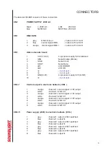
The decoder 3044BH consists of these connectors:
CN2
POWER SUPPLY 230V AC
black
L 230V AC
LIVE
230V AC
blue
N 230V AC
NEUTRAL 230V AC
CN1
DMX DATA
1
grey
GND, Screen
-> refers to Pin 1 XLR
2
blue
control signal DMX -
-> refers to Pin 2 XLR
3
orange
control signal DMX +
-> refers to Pin 3 XLR
CN3
Adress decoder board
1
VCC (+5.0V)
Logic power supply 5.0V stabilized
2
SEN
Serial Enable (Strobe)
3
SCLK
Serial Clock
4
SDAT
Serial Data
5
LD1
LED ERROR
6
LD2
LED OK
7
nc
- do not use! -
8
nc
- do not use! -
9
GND (0.0V)
Logic power supply 0.0V (GND)
10
nc
- do not use! -
CN4-7
Control output to electronic ballasts ( EVG )
1
orange
channel 1: control signal 1-10V output
2
white
channel 1: GND 0V
3
orange
channel 2: control signal 1-10V output
4
white
channel 2: GND 0V
5
orange
channel 3: control signal 1-10V output
6
white
channel 3: GND 0V
7
orange
channel 4: control signal 1-10V output
8
white
channel 4: GND 0V
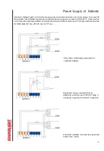
CN8-11
Power supply (230V) to electronic ballasts ( EVG )
1
grey
channel 1: output L 230V switched
2
blue
channel 1: output N
3
grey
channel 2: output L 230V switched
4
blue
channel 2: output N
5
grey
channel 3: output L 230V switched
6
blue
channel 3: output N
7
grey
channel 4: output L 230V switched
8
blue
channel 4: output N


