
5
Decoder Options
NOTE:
Using the new address setting board (order code: 3000P) will allow to set to set additional
parameters of the 3044B-H decoder. These functions include:
SWITCH #1
factory use only
SWITCH #2
OFF:Output to full ON when no DMX signal present
ON: Output to full OFF when no DMX sihnal present
SWITCH #3
OFF:4-channel operation
ON: 1-channel operation
SWITCH #4:
OFF:mains relays switch when input > 0%
ON: mains relays deactivated
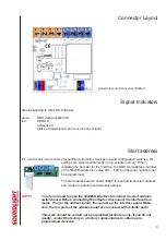
Control by DMX512
DMX512 will control four outputs, beginning with the programmed start address. Each output can be
operated individually. The start address can be set by the start address switch board. The unit may be
operated with or without start address board (then of course a start address must have been set before).
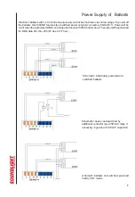
Electronic Ballasts (EVG)
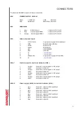
Control of electronic ballasts is via connectors CN4-7. There is one connector pair per output, with the
common output being GND (white, resp. light grey connector) for all connected ballasts.
Usually terminals on the electronic ballasts are designated "+" and "-" , respectively. Then "-" will mean
GND. Please note that the
maximum output current is limited to 25mA
per output. This means,
assuming a control current of 1mA per ballast:
The number of ballasts per drive output of the 3044A must not exceed 25 units in parallel.
If the ballasts require more input drive current the number of ballasts must be adjusted accordingly, e.g.
assuming 0.5 mA per ballast will allow 50 units, 3mA per ballast will allow 8 units.
The ballasts can be powerd from the switched AC outputs. The maximum load per output must not
exceed
200W
(that is 3x ballast 58W or 5x ballast 36W). If bigger loads must be switched, use a contactor
or relay being driven by the switched output of the 3044B-H..
Wiring of electronic ballasts shall only be performed by trained and skilled electricians. NOTE:
Interchanging power and data outputs will result in damaging connected components.
Please make absolutely sure that the wiring is correct before powering up the system!


