EVCS_Central Controller_ENGCC01241 5.16
1.800.338.7337 / www.soundoffsignal.com
NOTICE:
Installers and users must comply with all applicable federal, state and local laws regarding use and installation of warning devices.
Improper use or installation may void warranty coverage. To review our Limited Warranty Statement & Return Policy for this or any SoundOff Signal product, visit our website at
www.soundoffsignal.com/sales-support
. If you have questions regarding this product, contact
Technical Services
, Monday - Friday, 8 a.m. to 5 p.m. at
1.800338.7337
(press #4 to skip the
automated message). Questions or comments that do not require immediate attention may be emailed to
techservices@soundoffsigal.com.
SUPERIOR CUSTOMER RELATIONSHIPS. SMARTLY DESIGNED LIGHTING & ELECTRONIC SOLUTIONS.
1
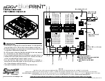
CENTRAL CONTROLLER
PART NUMBER: ENGCC01241
2
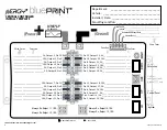
+
(Power)
-
(Ground)
Output #12 (F
use)
Output #11 (F
use)
Output #13 (F
use)
Output #14 (F
use)
Exterior Lightbar
Control Panel
USB
External Reset
Ignition
Input Node, 200R, up to 5 Remotes
Output #13 (10 Amps)
*
Output #14 (10 Amps)
*
Output #15 (5 Amps)
Output #16 (10 Amps)
Output #17 (5 Amps) Output #18 (10 Amps)
Output #19 (5 Amps)
Output #20 (5Amps)
Output #21 (10 Amps)
Output #22 (5 Amps)
Output #23 (10 Amps) Output #24 (5 Amps)
Output #12 (10 Amps)
*
Output #11 (10 Amps)
*
Output #10 (5 Amps)
Output #9 (10 Amps)
Output #8 (5 Amps)
Output #7 (10 Amps)
Output #6 (5 Amps)
Output #5 (5 Amps)
Output #4 (10 Amps)
Output #3 (5 Amps)
Output #2 (10 Amps) Output #1 (5 Amps)
AUTOMOTIVE 100A
FUSE OR BREAKER
V
BATT
DIRECT BATT GROUND
CONNECTION
POWER DIAGNOSTIC LED
2
* Constant Power Outputs
Internal Series Diode (to prevent backfeed
from external connections)
Higher inrush current threshold-
xenon
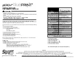
•HIGH CURRENT interconnects must be properly terminated. Poor crimp quality can
cause heat build-up and fire. Follow crimp connector manufacturer instructions.
•DO NOT install this product or route any wires in the Air Bag Deployment Zone. Refer
to vehicle Owner’s Manual for deployment zones.
•Do NOT use system to disconnect headlights, brake lights or other safety equipment.
•Unit may become hot to touch during normal operation.
•Failure to properly install connectors, fuses or wiring may cause vehicle failure or fire.
•Installation must only be performed by trained technician. Installer must determine
vehicle wiring configuration and proper integration of system.
•Use proper wire gauge. All power wires connecting to positive (+) or negative (-)
battery terminal or local chassis ground (-) must be sized to supply at least 125% of
max. current and properly fused at power source.
•Install protective grommets when routing wire through firewall or metal.
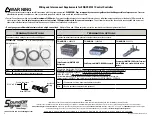
WARNING
Future Use


