ADLY-4/B User Guide
Page 8
Interconnection
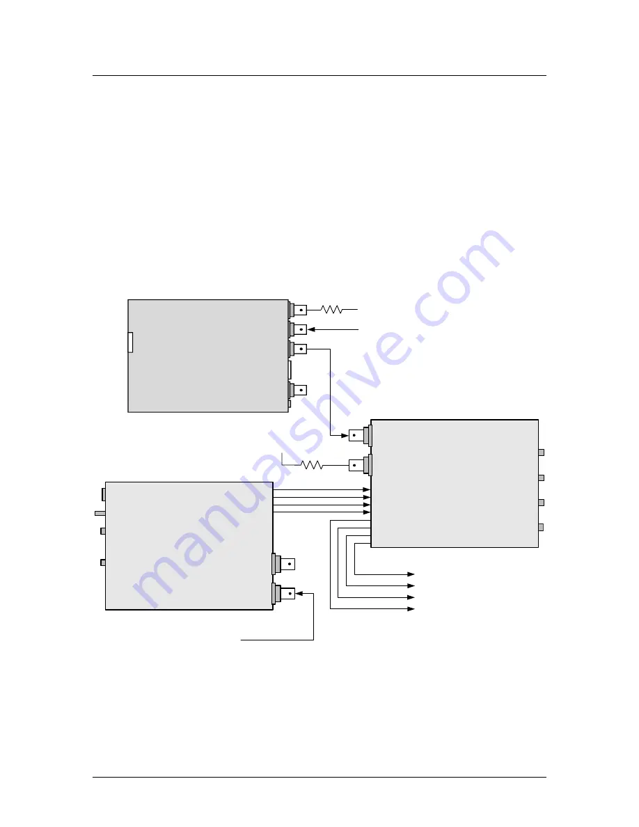
This section provides a typical ADLY-4/B interconnection diagram.
•
De-embedding and
Delaying Embedded Audio
In this application, a house NTSC reference is connected to the VRG-1 SoundPal to
create an AES3id reference signal that is locked to the house NTSC signal. This AES3id
signal is then routed to the External Reference AES3id BNC input on the ALDY-4/U. Its
loop-thru output is then terminated. The Reference Selection Switch is set to the down
position to lock the ADLY-4/B to the external BNC AES3id inputs and the FPS is then set
to 30 frames to be frame accurate to the NTSC signal. A synchronous SDI TV signal with
the embedded audio to be delayed is then fed to an AEDM-4/SD SoundPal. This
SoundPal de-embeds any two of the four channel groupings into 8 channels (four AES3id
channel pairs) of synchronous audio. This audio is then fed to the ADLY-4/B SoundPal
Delay module. The output of the ADLY-4/B Delay module then provides the 8 Channels
(4 AES3id Channel Pairs) of audio delayed by the amount of frames set by the three
Delay-Frame Switches and locked to the house NTSC reference.
AES3id
Loop Thru
AES3id
Inputs
8 Channels
Delay-Frame
Switches
X.1
SoundPals
ADLY-4/B
X1
X10
FPS
Switch
AES3id
Outputs
8 Channels
G
ro
u
p
A
B
H e a d p h o n e
V o l u m e
SoundPals
AEDM-4/SD
AES3id
Outputs
8 Channels
SDI Video
Out
SDI Video
In
Delayed
AES3id Audio
To Destination
Termination
Synchronous
SDI TV Signal with
Embedded Audio
Mode
Switch
PWR
Word Clock Out
AES Out
AES3ID Out
Video In
Loop
Termination
SoundPals
VRG-1
NTSC House Reference
Note: It is possible in this setup to lock the ADLY-4/B to the Channel 1 input by placing
the Reference Selection Switch to the up position, therefore eliminating the VRG-1. If the
Channel 1 AES3id Data stream is consistent this will work just fine. If not for stability
reasons, it is suggested that an external AES3id sync to insure the AES3id input
receivers remained locked even with the loss of the AES3id data stream.


