5
Index
1. Description ......................................................................................................... 6
2. Control panel ..................................................................................................... 8
2.1. Connections and items ............................................................................... 8
2.2. Keyboard .................................................................................................... 9
3. Power supply ................................................................................................... 10
3.1. Battery / battery charger ........................................................................... 10
3.1.1. Battery description ............................................................................. 10
3.1.2. Battery status check ........................................................................... 10
3.1.3. Recharge procedure........................................................................... 10
4. Printer .............................................................................................................. 11
5. Connecting the TM-25R ................................................................................... 12
5.1. Equipment location ................................................................................... 12
5.2. Auxiliary rods set up ................................................................................. 12
6. Measuring ........................................................................................................ 13
6.1. Selecting the type of measurement ........................................................... 13
6.1.1. Grounding resistance measurement ................................................... 13
6.1.2. Grounding resistance measurement function with inductive component
compensation .............................................................................................. 13
6.2. Looking for the potential profile flat area ................................................... 15
6.3. Guard wire inductance .............................................................................. 15
7. Abnormalities indications on the display ........................................................... 16
7.1. Excessively high earth resistance ............................................................. 16
7.2. Excessively high resistance in the auxiliary rods ....................................... 16
8. Auto power-off ................................................................................................. 16
9. Software .......................................................................................................... 17
9.1. USB Drivers .............................................................................................. 17
9.2. ST-Logger software .................................................................................. 17
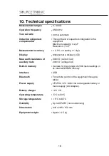
10. Technical specifications ................................................................................. 18
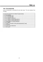
10.1. Accessories ............................................................................................ 19
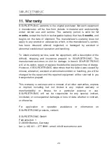
11. Warranty ........................................................................................................ 20


