ST1952 Operation Manual
13
2.3 Rear Panel Summary
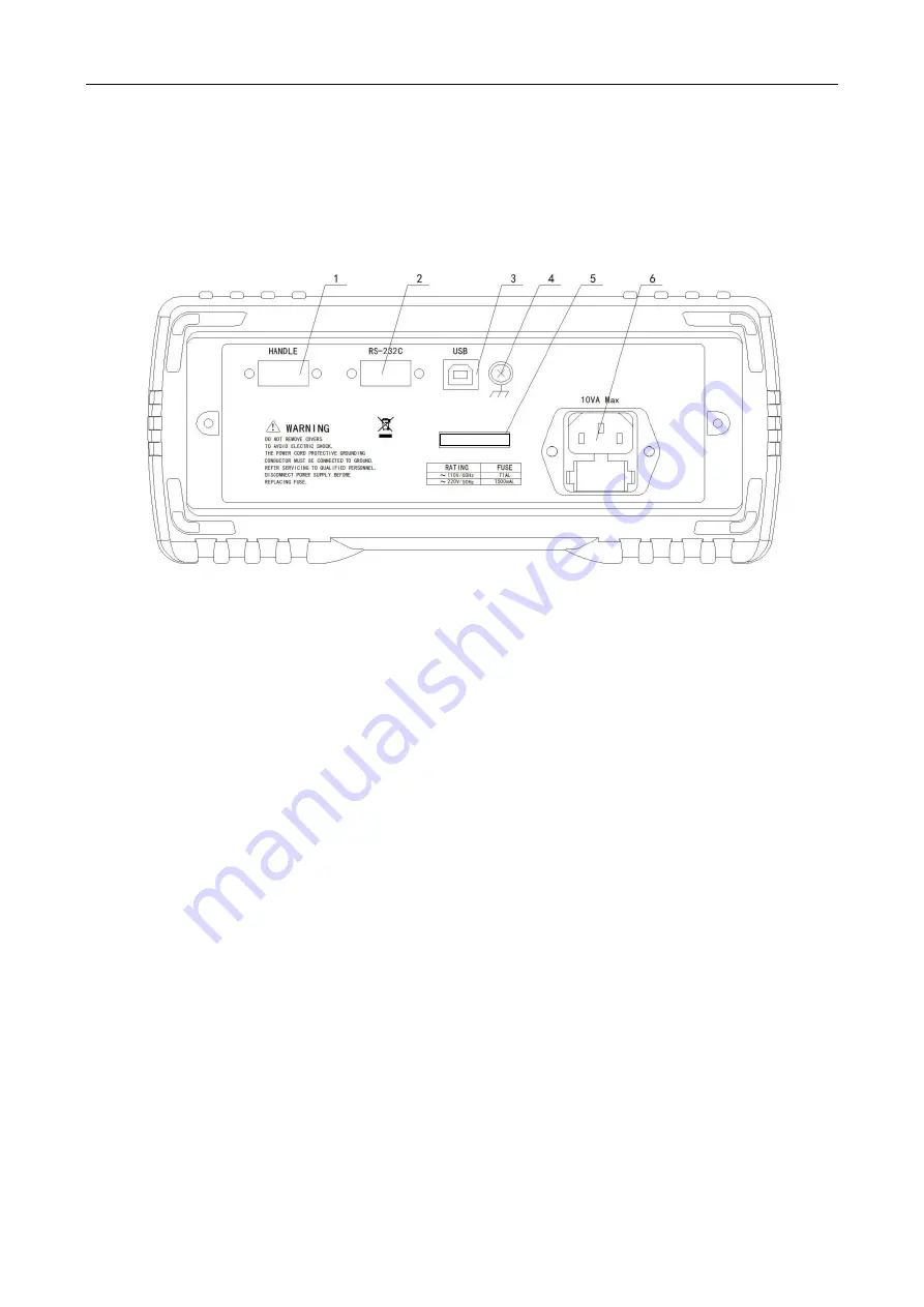
The rear panel of ST1952 is shown in Figure 2-4. This section includes important information that should
be reviewed before operating the instrument.
Figure 2-4 ST1952 Rear Panel
1. HANDLER interface
Use a standard DB-9 hole-type connector. Use external signal to trigger test
2. RS-232C Connector
Use a standard DB-9 needle-type connector for RS-232 operation.
3. USB interface
Use a USB-B square connector. Use USB wire for remote operation.
4. Grounding
Chassis Grounding terminal
5. Label
Serial number for this instrument
6. Power-Line Fuse-Holder Assembly
ST1952 can be configured for line voltage of 110/220V±10% AC at line frequency of 50/60Hz±5%.
Power-line fuse is used for instrument protection. (220V/500mA or 110V/1A)
Note: Please use the same-type fuse or contact your nearest Sourcetronic sales and service
office. To verify and replace the fuse, remove the power cable and pull out the fuse
holder.


